Setup
MediaandAdditionalParts
Description
Qty.
Use
Starterkey
2
Operator'sManual
1
Engineowner'smanual1
PartsCatalogInstructionCard
1
Operatortrainingmaterials
1
Screenlter
2
Readthemanualsandwatchthetrainingmaterialsbefore
operatingthemachine.
Note:Determinetheleftandrightsidesofthemachinefromthenormaloperatingposition.
Note:Ifyouhavequestionsorneedadditionalinformationregardingthespraycontrolsystem,refertothe
Operator’sManualsuppliedwiththesystem.
Important:Thissprayerissoldwithoutspraynozzles.
Tousethesprayer,youmustobtainandinstallthenozzles.ContactyourauthorizedTorodistributorfor
informationontheavailablesectionkitandaccessories.
Afteryouinstallyournozzlesandbeforeusingthesprayerforthersttime,adjustthesectionbypass
valvessothatthepressureandapplicationrateremainsthesameforallsectionswhenyouturn1or
moresectionsoff.RefertoCalibratingtheSection-BypassValves(page28).
1
InstallingtheAnti-Siphon
FillReceptacle
Partsneededforthisprocedure:
1
90°tting
1
Quickcoupler
1Hoseadapter
1Fill-receptaclebracket
1
Flange-headbolt(5/16x3/4inch)
1Anti-siphonhose
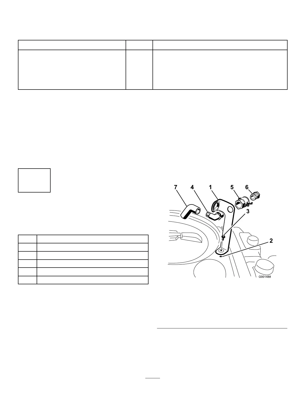
Procedure
1.Placethell-receptaclebracketoverthe
threadedholeinthetankandsecureitwitha
ange-headbolt(5/16x3/4inch)asshownin
Figure3.
g001488
Figure3
1.Fill-receptaclebracket
5.Quickcoupler
2.Threadedholeinthetank6.Hoseadapter
3.Flangebolt(5/16x3/4
inch)
7.Anti-siphonhose
4.90°elbowtting
2.Placethethreadedendofthe90°elbowtting
throughthebracketandthreadthequickcoupler
ontoit,securingittothebracket(Figure3).
Note:Installthettingwiththeopenend
pointingtowardthelargeopeninginthebracket
12