andtowardthetankopeningsothatthewater
arcsintothetankwhenyoullit.
3.Installthehoseadapterintothequickcoupler
(Figure3).
4.Locktheadapterintoplacebyswingingthe
leverstowardtheadapterandthensecurethem
withthehairpincotters(Figure3).
5.Installtheanti-siphonhosethroughthelarge
openingonthebracketandontothebarbedend
ofthe90°elbowtting(Figure3).
Important:Donotlengthenthehoseto
allowcontactwiththetankuids.
2
CheckingtheSection-Hinge
Springs
NoPartsRequired
Procedure
Important:Operatingthespraysystemwith
thesection-hingespringsundertheincorrect
compressioncoulddamagetheboomassembly.
Measurethespringsandusethejamnutto
compressthespringsto4cm(1-1/2inches)if
necessary.
Thesprayerisshippedwiththesectionextensions
swungforwardtofacilitateshippingthemachine.
Thespringsarenotfullytightenedatthetimeof
manufacturetoallowthesectionstobeinthisposition
fortransit.Beforeoperatingthemachine,thesprings
mustbeadjustedtothecorrectcompression.
1.Ifnecessary,removethepackingcomponents
thatsecuretherightandleftextensionsections
duringshipping.
2.Supportthesectionswhiletheyareextendedto
thesprayposition.
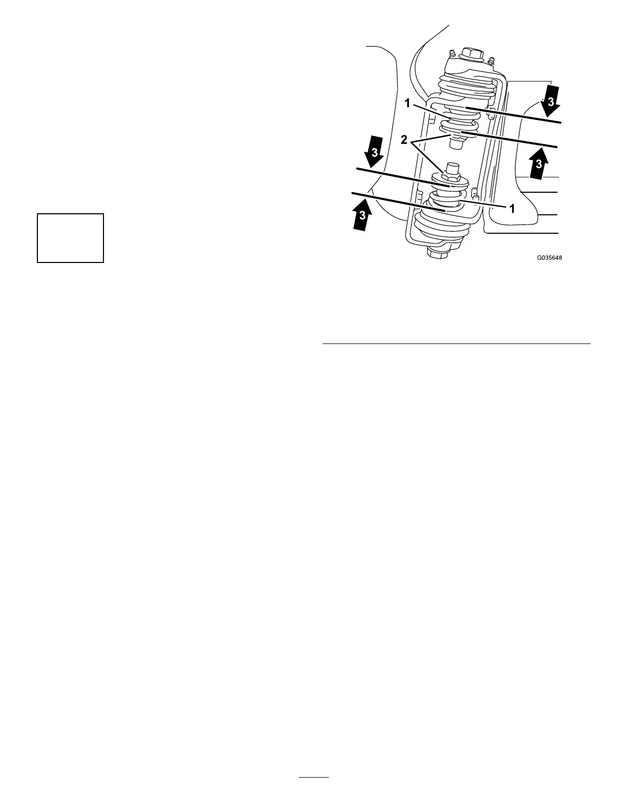
3.Atthesectionhinge,measurethecompression
oftheupperandlowerspringswhilethesections
areintheirextendedposition(Figure4).
A.Allspringsmustbecompresseduntilthey
measure4cm(1-1/2inches).
B.Usethejamnuttocompressanyspringthat
measuregreaterthan4cm(1-1/2inches).
g035648
Figure4
1.Section-hingespring3.Compressedspring
dimension—4cm(1-1/2
inches)
2.Jamnut
4.Repeattheprocedureforeachspringonboth
sectionhinges.
5.Movethesectionsintothetransport‘X’position.
SeePositioningtheSpraySections(page34)
formoreinformation.
13