48–54and60InchCasterDisassembly
g318028
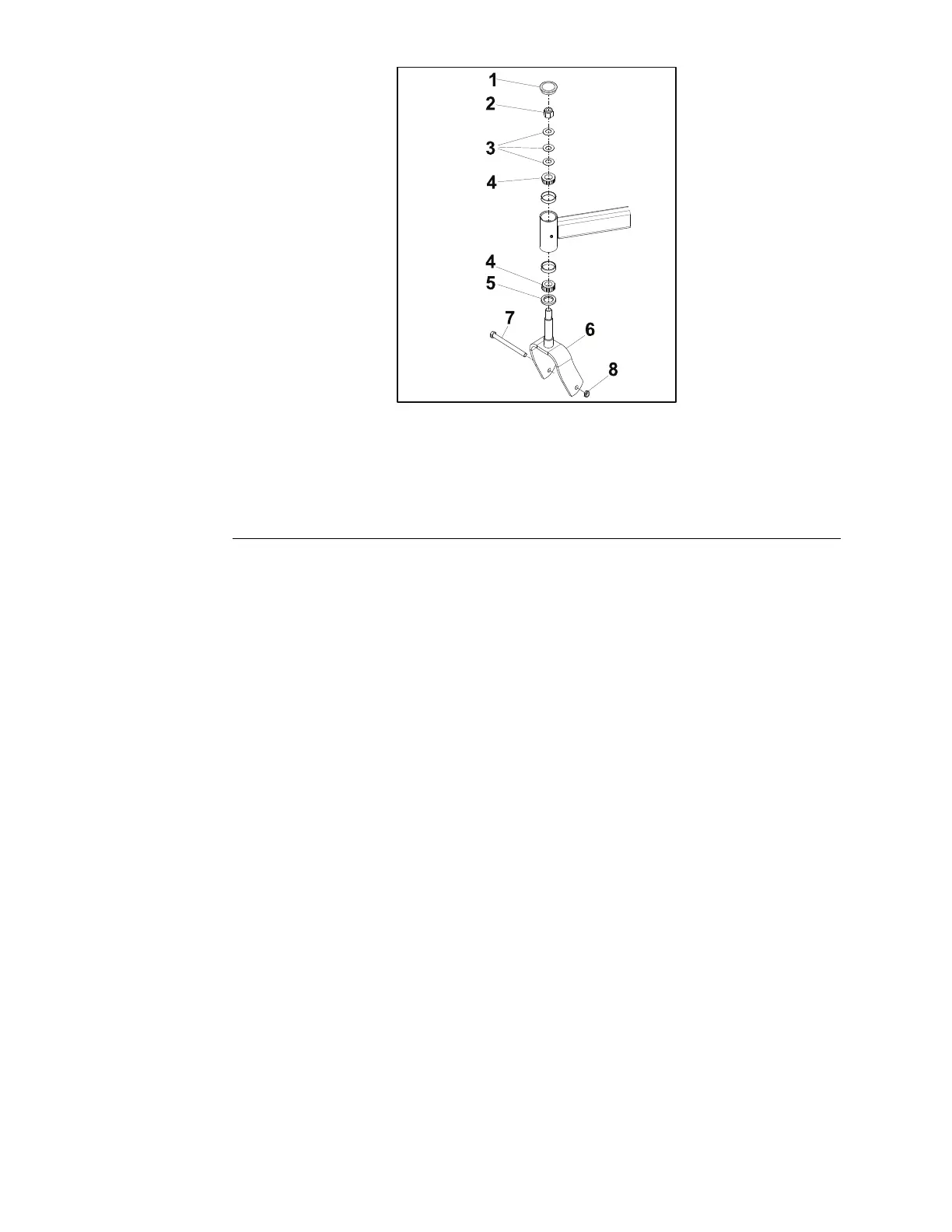
Figure58
1.GreaseCap5.GreaseSeal
2.NILockNut
6.CasterFork
3.BellvilleWashers
7.HHScrew
4.T aperedRollerBearing
8.HexNut
1.Parkthemachineonalevelsurfaceandsettheparkingbrake.Stopthe
engine,waitforallmovingpartstostopandremovethekey.
2.Disconnectthebatterybyremovingthenegativebatterycablerst,then
thepositivecablefromthebattery.
3.Removethegreasecap(item1)fromthetopofthecasterwheelpivottube.
4.Removethelocknut(item2)fromthecasterforkshaft.
5.Removethecasterfork(item6)andwheelassembly.
6.Removethe3Bellevillewashers(item3)fromthecasterwheelpivottube.
7.Removetheuppertaperedrollerbearing(item4)fromthecasterwheel
pivottube.
8.Removethegreaseseal(item5)fromthebottomofthecasterwheelpivot
tube.Removethelowertaperedrollerbearing.
9.Usingabluntpunch,removetheupperandlowerbearingcupsfromthe
casterwheelpivottube.
10.Removethenutsecuringthecasterwheelaxlebolt.Removetheaxlebolt.
11.Removethecasterwheelassemblyfromthecasterfork.
12.Removethesealguardfrombothsidesofthewheelhub.
13.Removethespacernutfromthecasteraxle.
Note:Thespacernutsareboththreadedontothecasteraxle.Oneofthe
spacernutswillneedtoberemovedafterithasbeenremovedfromthe
casterwheel.
14.Removethegreasesealfrombothsidesofthecasterwheel.
15.RemovetheLHandRHtaperedbearings.
48–54and60InchAssembly
1.Packthecasterwheeltaperedrollerbearingwithhightemperaturegrease.
Chassis:ServiceandRepairs
Page5–8
PROLINE®ServiceManual
3431-988RevA