2
Installing the Roll Bar
Parts needed for this procedure:
1 Roll bar
6
Flange-head bolt (1/2 x 1-1/4 inches)
Procedure
1. Apply medium-grade (service-removable)
thread-locking compound to the threads of the 6
ange-head bolts (1/2 x 1-1/4 inches).
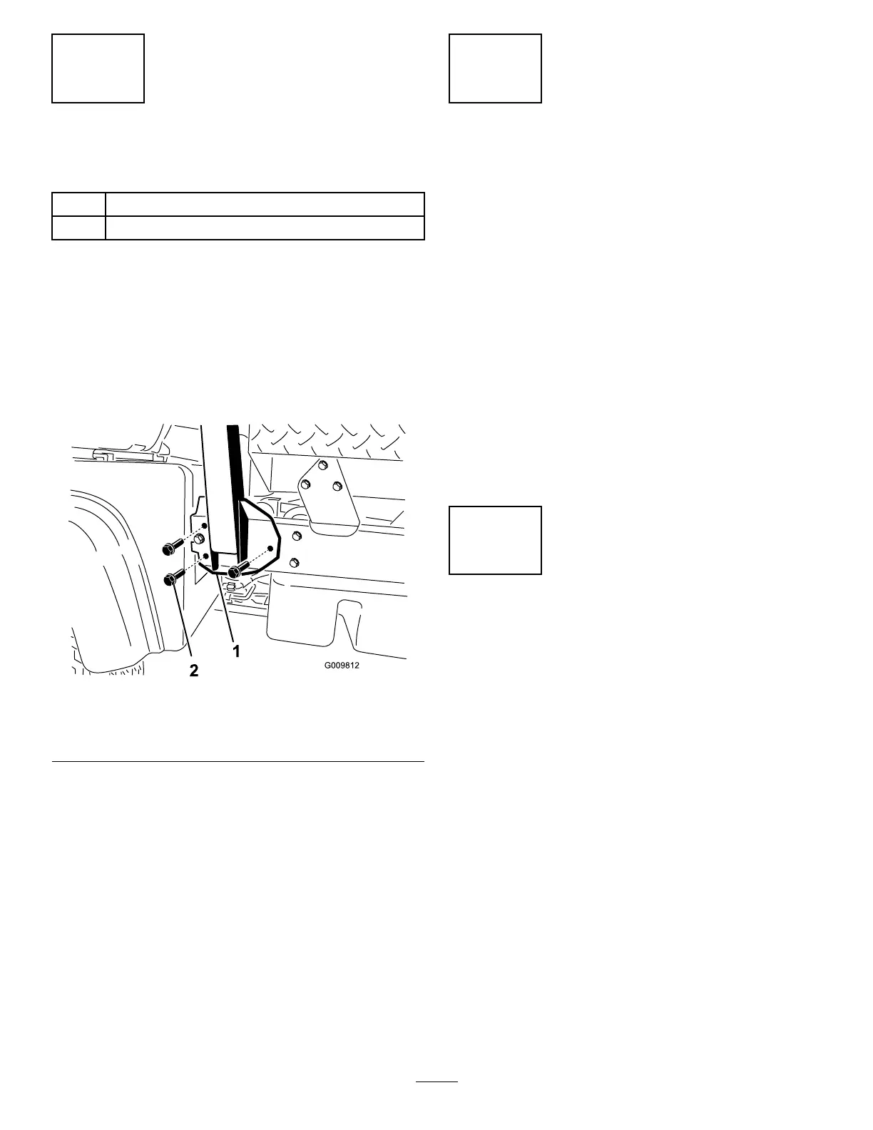
2. Align each side of the roll bar with the mounting
holes on each side of the machine frame ( Figure
4 ).
g009812
Figure 4
1. Roll bar mounting bracket
2. Flange-head bolt (1/2 x
1-1/4 inches)
3. Secure the roll bar mounting bracket to the
machine frame using 3 ange-head bolts (1/2 x
1-1/4 inches) on each side ( Figure 4 ).
4. T orque the ange-head bolts (1/2 x 1-1/4 inches)
to 1 15 N∙m (85 ft-lb).
3
Checking the Fluid Levels
and T ire Pressure
No Parts Required
Procedure
1. Check the engine-oil level before and after
you rst start the engine; refer to Checking the
Engine-Oil Level ( page 42 ) .
2. Check the transaxle/hydraulic-uid level before
you rst start the engine; refer to Checking the
T ransaxle/Hydraulic-Fluid Level ( page 57 ) .
3. Check the brake-uid level before you rst start
the engine; refer to Checking the Brake-Fluid
Level ( page 53 ) .
4. Check the air pressure in the tires; refer to
Checking the T ire Pressure ( page 21 ) .
4
Burnishing the Brakes
No Parts Required
Procedure
T o ensure optimum performance of the brake system,
burnish the brakes before use.
1. Bring the machine up to full speed, apply the
brakes to rapidly stop the machine without
locking up the tires.
2. Repeat this procedure 10 times, waiting 1 minute
between stops, to avoid overheating the brakes.
Important: This procedure is most effective
if the machine is loaded with 454 kg (1,000
lb).
13