Servicing the High-Flow
Hydraulic System
TC Models Only
Hydraulic Fluid Specications
The reservoir is lled at the factory with high-quality
hydraulic uid. Check the level of the hydraulic uid
before you rst start the engine and daily thereafter;
refer to Checking the High-Flow Hydraulic-Fluid Level
( page 60 ) .
Recommended replacement uid: T oro PX
Extended Life Hydraulic Fluid; available in 19 L (5 US
gallon) pails or 208 L (55 US gallon) drums.
Note: A machine using the recommended
replacement uid requires less frequent uid and lter
changes.
Alternative uids: If T oro PX Extended Life
Hydraulic Fluid is not available, you may use another
conventional, petroleum-based hydraulic uid having
specications that fall within the listed range for all the
following material properties and that it meets industry
standards. Do not use synthetic uid. Consult with
your lubricant distributor to identify a satisfactory
product.
Note: T oro does not assume responsibility for
damage caused by improper substitutions, so use
products only from reputable manufacturers who will
stand behind their recommendation.
High V iscosity Index/Low Pour Point
Anti-wear Hydraulic Fluid, ISO VG 46
Material Properties:
V iscosity , ASTM D445 cSt @ 40°C (104°F)
44 to 48
V iscosity Index ASTM D2270
140 or higher
Pour Point, ASTM D97 -37°C to -45°C (-34°F
to -49°F)
Industry Specications: Eaton V ickers 694 (I-286-S,
M-2950-S/35VQ25 or
M-2952-S)
Note: Many hydraulic uids are almost colorless,
making it dif cult to spot leaks. A red dye additive for
the hydraulic uid is available in 20 ml (0.67 oz)
bottles. A bottle is suf cient for 15 to 22 L (4 to 6 US
gallons) of hydraulic uid. Order Part No. 44-2500
from your authorized T oro distributor .
Checking the High-Flow
Hydraulic-Fluid Level
TC Models Only
Service Interval : Before each use or daily —Check
the high-ow hydraulic-uid level
(TC models only). (Check the level
of hydraulic uid before the engine
is rst started, and daily thereafter)
1. Park the machine on a level surface.
2. Engage the parking brake.
3. Shut of f the engine and remove the key .
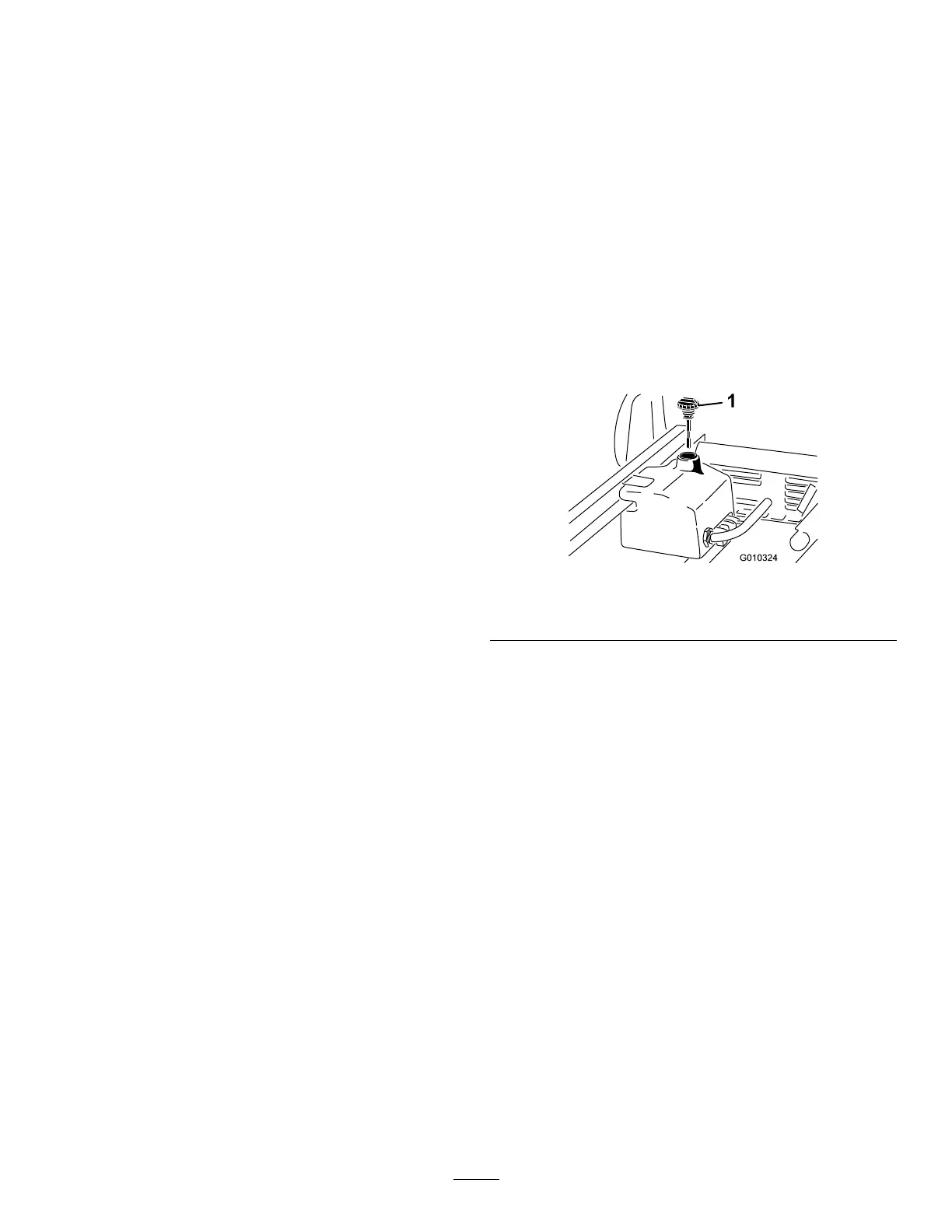
4. Clean the area around the ller neck and the
cap of the hydraulic tank ( Figure 70 ).
5. Remove the cap from the ller neck.
g010324
Figure 70
1. Cap
6. Remove the dipstick ( Figure 70 ) from the ller
neck and wipe it with a clean rag.
7. Insert the dipstick into the ller neck, then
remove it and check the uid level.
Note: The uid level should be between the 2
marks on the dipstick.
8. If the level is low , add the appropriate uid
to raise the level to the upper mark; refer to
Changing the High-Flow Hydraulic Fluid and
Filter ( page 61 ) .
9. Install the dipstick and cap onto the ller neck.
10. Start the engine and turn on the attachment.
Note: Let them run for about 2 minutes to purge
air from the system.
Important: The machine must be running
before starting the high-ow hydraulics.
1 1. Shut of f the engine and attachment and check
for leaks.
60