Adjusting the Accelerator
Pedal
1. Park the machine on a level surface, engage the
parking brake, shut of f the engine, and remove
the key .
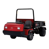
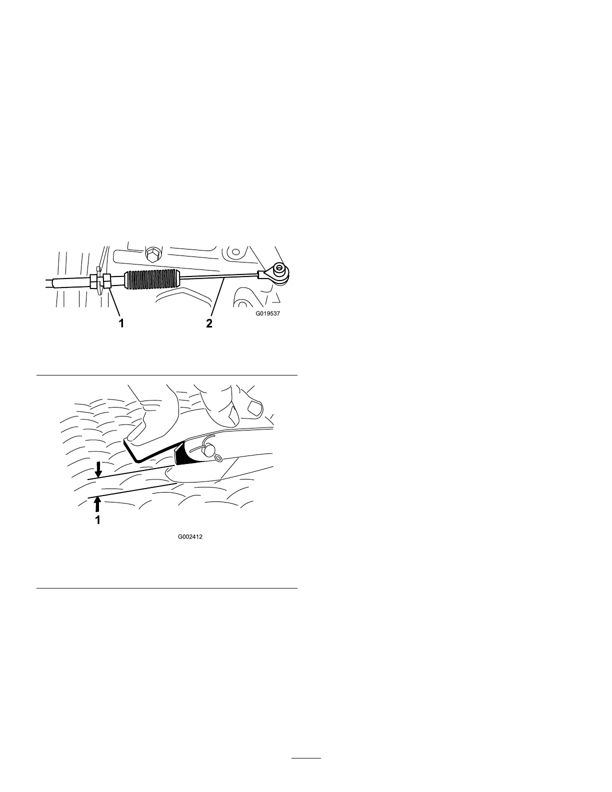
2. Adjust the ball joint on the accelerator cable
( Figure 64 ) to allow 2.54 to 6.35 mm (0.100 to
0.250 inch) of clearance between the accelerator
pedal arm and the top of the diamond tread oor
plate ( Figure 65 ), when you apply 1 1.3 kg (25 lb)
of force to the center of the pedal.
Note: The engine must not be running and the
return spring must be attached.
3. T ighten the locknut ( Figure 64 ).
g019537
Figure 64
1. Locknut 2. Accelerator cable
g002412
Figure 65
1. 2.54 to 6.35 mm (0.100 to 0.250 inch) clearance
Important: The maximum high-idle speed is 3,650
rpm. Do not adjust the high-idle stop.
Hydraulic System
Maintenance
Hydraulic System Safety
• Seek immediate medical attention if uid is injected
into skin. Injected uid must be surgically removed
within a few hours by a doctor .
• Before disconnecting or performing any work on
the hydraulic system, relieve all pressure in the
system by shutting of f the engine, cycling the
dump valve from raise to lower , and/or lowering
the cargo bed and attachments. Place the remote
hydraulics lever in the oat position. Do not work
under a raised bed without the proper bed safety
support in place.
• Ensure that all hydraulic-uid hoses and lines are
in good condition and that all hydraulic connections
and ttings are tight before applying pressure to
the hydraulic system.
• Keep your hands and body away from pinhole
leaks or nozzles that eject high-pressure hydraulic
uid.
• Use cardboard or paper to nd hydraulic leaks.
Servicing the
T ransaxle/Hydraulic
System
T ransaxle/Hydraulic Fluid
Specications
T ransaxle-uid type: Dexron III A TF
Checking the
T ransaxle/Hydraulic-Fluid Level
Service Interval : Before each use or daily —Check
the transaxle/hydraulic-uid level.
(Check the uid level before the
engine is rst started and every 8
hours or daily , thereafter .)
1. Park the machine on a level surface.
2. Engage the parking brake.
3. Shut of f the engine and remove the key .
4. Clean the area around the dipstick ( Figure 66 ).
57