g009822
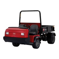
Figure 71
1. Quick-coupler hose A
2. Quick-coupler hose B
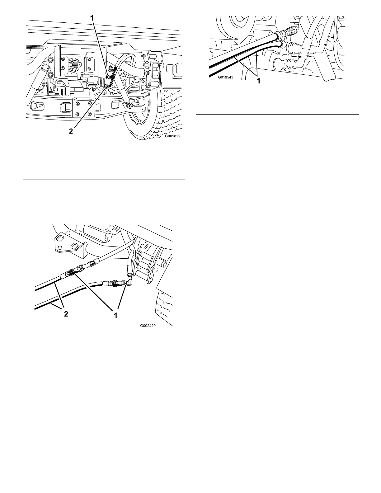
3. On the disabled machine, connect the 2 jumper
hoses to the hoses that were disconnected
( Figure 72 ).
4. Cap the unused ttings.
g002429
Figure 72
1. Disconnected hoses 2. Jumper hoses
5. On the other machine, connect the 2 hoses to
the coupler still in the coupler bracket (connect
the top hose to the top coupler and the bottom
hose to the bottom coupler) ( Figure 73 ).
6. Cap the unused ttings.
g019543
Figure 73
1. Jumper hoses
7. Keep all bystanders away from the machines.
8. Start the second machine and move the lift lever
to the raise position, which raises the disabled
cargo bed.
9. Move the hydraulic-lift lever to the N EUTRAL
position, and engage the lift-lever lock.
10. Install the bed support onto the extended lift
cylinder; refer to Using the Bed Support ( page
35 ) .
Note: With both the machine turned of f, move
the lift lever back and forth to remove the system
pressure and ease the disconnection of the
quick couplers.
1 1. After completing the operation, remove the
jumper hoses and connect the hydraulic hoses
to both machines.
Important: Check the hydraulic uid
levels, in both machines, before resuming
operation.
62