–5–
Installation Manual
4 About installation
Installation location and installation dimensions
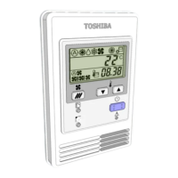
• Install the remote controller at a height of 3′3″ to 4′9″ (1 to 1.5 m) from the floor in a location that seems to be the
average temperature of the room.
• Do not install the remote controller in a place where it will be exposed to direct sunlight or outside air (near a
window or the like).
• Do not install the remote controller behind obstacles or where it is blocked from air flowing in the room.
• The remote controller is not built to waterproof or humidity-proof specifications, so do not install it in a freezer or
refrigerator.
• Install the remote controller vertically on a wall, or the like.
Remote controller wiring and remote controller inter-unit wiring
The remote controller wiring (communication line) and AC208 - 240 V wires cannot make contact with each other
and cannot be put in the same conduits. It may cause problems in the control system due to noise or other factors.
* Varies depending on the remote controller used.
Cable type VCTF: AWG20 to AWG14 (0.5 mm² to 2.0 mm²) × 2
Total wire length of remote controller
wiring and remote controller inter-unit
wiring
(L + L1 + L2 + …Ln)
1 remote controller 2 remote controllers
2 remote controllers
(wireless and wired)
Up to 1640 ft (500 m) Up to 980 ft (300 m) Up to 1310 ft (400 m)
Total wire length of remote controller
inter-unit wiring
(L1 + L2 + …Ln)
Up to 660 ft (200 m)
Room temperature
sensor
4.72 (120)
0.78 (20)
4.72 (120)
4-Ø0.17×0.31 (4-Ø4.2×8) oval hole
0.94
(24)
0.86 (22)
1.65
(42)
1.65
(42)
(Unit: inch (mm))
Remote controller
wiring
L
L1 L2 Ln
(Max 8 units)
(Max 16 units: For TU2C-LINK)
Indoor unit
Remote controller inter-unit wiring
Indoor unit Indoor unit Indoor unit
Remote controller
 Loading...