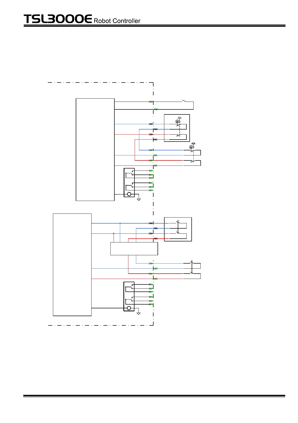
4.2 Detail of SAFE Circuit
TSL3000E/TSL3100E controller
Emergency stop latch reset input
Customer-prepared
IN -E MG1
OU-EMG1
IN -E MG2
OU-EMG2
External emergency stop switch
Customer-prepared
Emergency stop switch
Enable switch
Teach pendant (TP1000)
External emergency stop switch
Customer-prepared
P24G
Emergency stop status output
c-contact redundant output
P24G
Teach pendant (TP1000)
Mode monitor
Emergency stop
signal monitor
Safety door and
enable signal
monitor
RST-1
RST-2
EMG-IN1
EMG-OUT1
EMG-IN2
EMG-OUT2
SAD-IN1
SAD-OUT1
SAD-IN2
SAD-OUT2
Emergency stop status output
c-contact redundant output
SAFE
SAFE
SAFE
TP
TP
1
2
3
4
5
6
13
14
15
16
7
8
9
11
12
10
17
18
19
21
22
20
Fig. 4.1 Safety I/O circuit
 Loading...