– 43 –
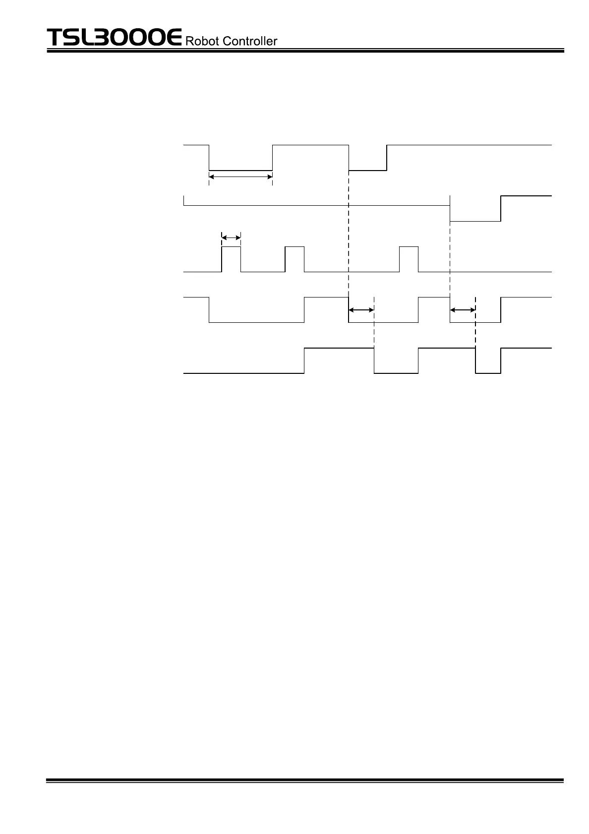
4.5 SAFE Circuit Operation Timing
EMG-IN1,2~
EMG-OUT1,2
RST-1,2
Alarm
SAD-IN1,2~
SAD-OUT1,2
500msec
Emergency stop
150msec
close
none
Servo power circuit
open
500msec
close
open
4.5.1 Start Method
While all emergency stop switches are canceled, the safety relay module in the
controller is reset by pressing the switch between RST-1 and RST-2. Set the input
width of RST-1 and RST-2 signals to 150 ms (min.) or more. When the safety relay
module is reset, the alarm and servo power circuit enter close status and AC power
is connected to the servo power unit.
Then, voltage charge is started and power is supplied to the motor by inputting the
servo ON command signal.
4.5.2 Stop Method
The stop method varies depending on the status of the master mode switch on the
control front panel.
In TEACH mode, when any of the emergency stop switch, enable switch on the
teach pendant and safety input switch is open, slowdown and stop are started, the
brake signal is then input, and the power to the motor is turned off. In EXT mode,
the enable switch on the teach pendant is disabled, and the robot does not stop
even if the enable switch on the teach pendant is gripped.
When a delay time of 500 ms elapses after any of the emergency stop switch,
enable switch on the teach pendant and safety input switch is open, the servo power
 Loading...