1
20
2
21
3
22
4
23
5
24
6
25
7
26
8
27
9
28
10
29
11
30
12
31
13
32
14
33
15
34
16
35
17
18
19
36
37
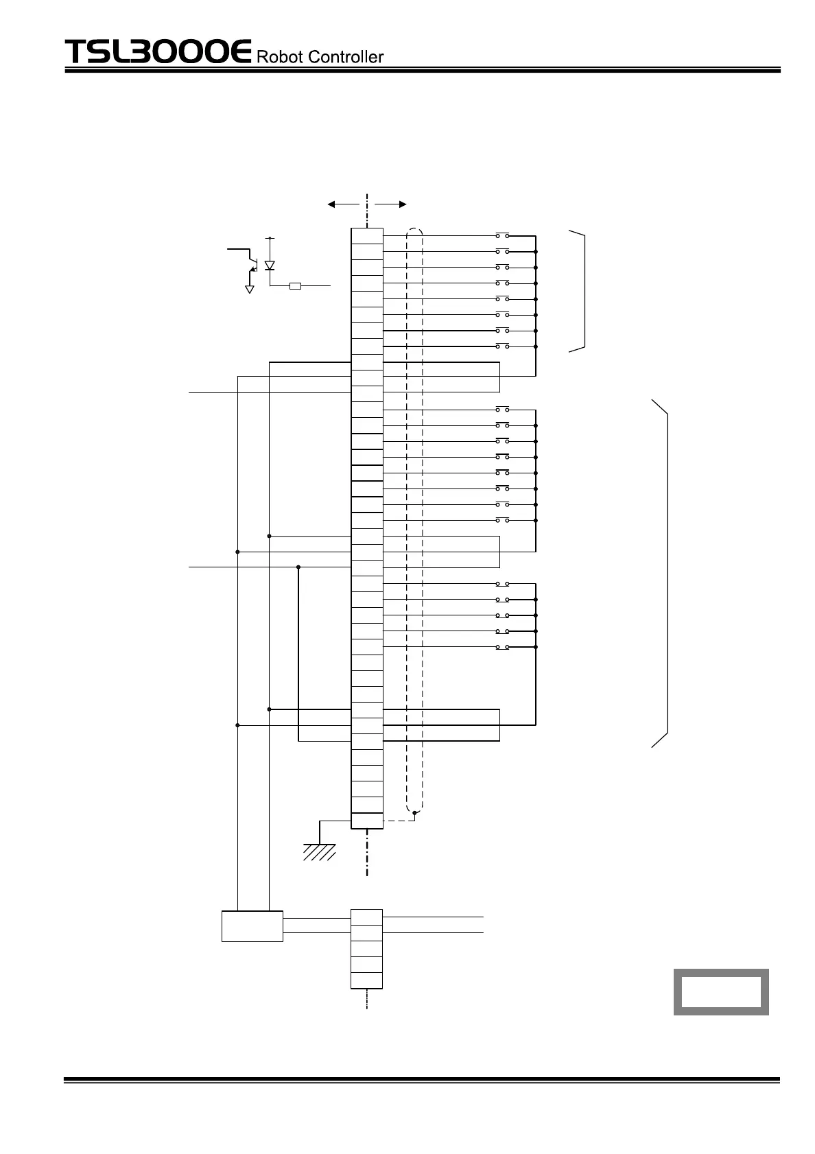
Case
System
input signal
(1)
(2)
(3)
(4)
User side
(6)
(7)
(8)
DI_1
DI_2
DI_3
DI_4
DI_5
DI_6
DI_7
DI_8
P24V
P24G
INCOM
STROBE
PRG_ RST
STEP_RST
CYC_ RST
DO_ RST
ALM_RST
RUN
EX_SVON
P24V
P24G
SYSINCOM
XM3A-3721
(Dsub-37S)
Robot controller
FG
(5)
( ) Signal name of DIN command
Connector
(INPUT)
P24G
SYSINCOM
P24V
(257 )
(258 )
( 259)
(260 )
(261 )
Digital input signal
STOP
CYCLE
LOW_SPD
BREAK
SVOFF
Stop
Cycle mode
Low speed command
Deceleration and stop
Servo off
Strobe
Program reset
Step reset
Cycle reset
Output signal reset
Alarm reset
Start
External servo ON
(249 )
(250 )
(251 )
(252 )
(253 )
(254 )
(255 )
(256 )
INCOM,
SYSINCOM
Note: To use the INPUT and OUTPUT signals,
supply P24V from the external equipment.
Unless power is input from the EXT I/O connector
on the front panel, an error occurs in the
detection circuit.
DI_*
INCOM
*In the figure, an example is shown where
common signals (INCOM and SYSINCOM)
are connected to P24V.
5
4
IN_P24V
Connector
(EXT I/O)
SYSINCOM
3
2
1
IN_P24G
External power
supply detection
circuit
*Common for digital
input
*Common for system
input
Fig. 4.3 Connection of external input signal cable (Type N)
 Loading...