1
14
2
15
3
16
4
17
5
18
6
19
7
20
8
21
9
22
10
23
11
24
12
25
13
CASE
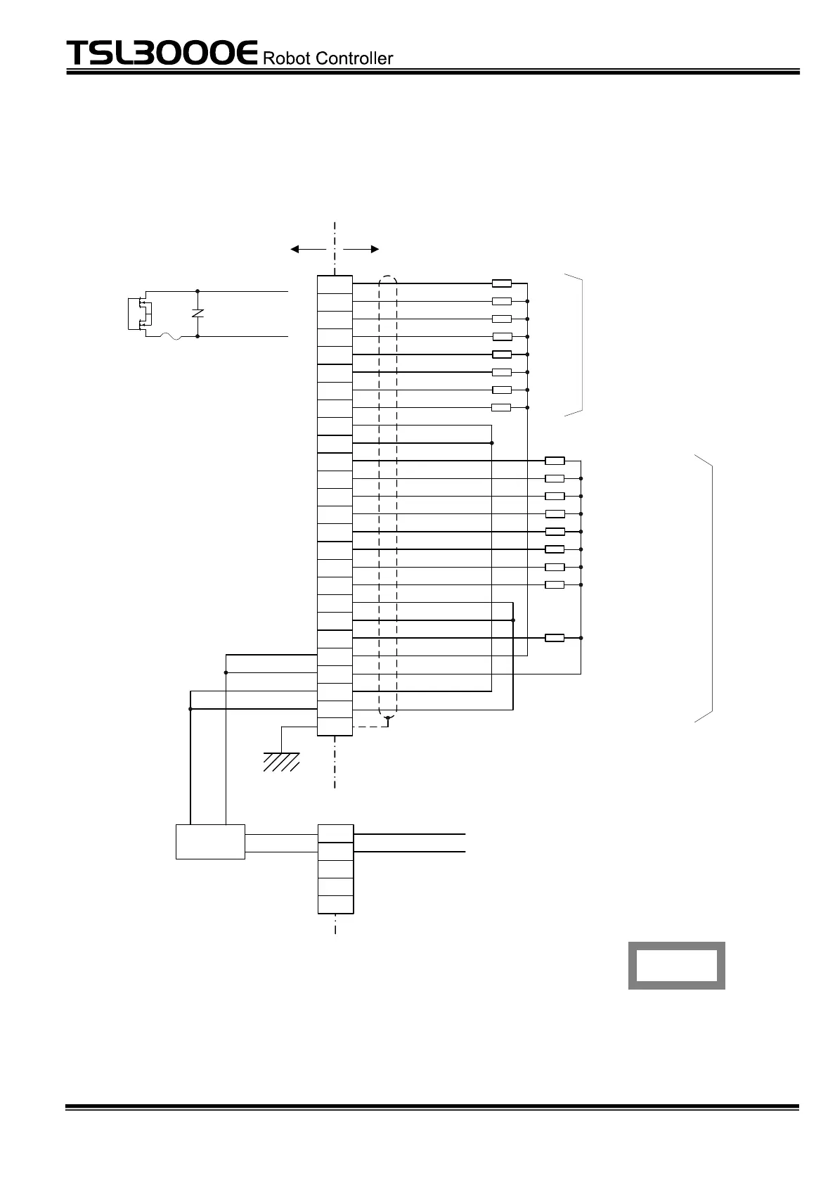
User side
XM3A - 2521
( Dsub- 25S)
Robot controller
FG
Connector
(OUTPUT)
( ): Signal name of DOUT command
(1)
(2)
(3)
(4)
(6)
(7)
(8)
DO_1
DO_2
DO_3
DO_4
DO_5
DO_6
DO_7
DO_8
OUTCOM
ACK
SV_RDY
SYS_RDY
AUTORUN
CYC_END
LOW_ST
BT_ ALM
(5)
Digital output signal
ALARM
System
output
signal
Acknowledge
゙
Servo ready
External mode ON
System ready
Auto mode ON
Cycle end
Low speed mode ON
Battery alarm
Alarm
OUTCOM
SYSOUTCOM
SYSOUTCOM
P24V
P24V
P24G
P24G
DO_*
OUTCOM,
SYSOUTCOM
Connector
(EXT I/O)
External power
supply detection
circuit
5
4
3
2
1
Note: To use the INPUT and OUTPUT signals,
supply P24V from the external equipment.
Unless power is input from the EXT I/O connector
on the front panel, an error occurs in the detection
circuit.
IN_P24V
IN_P24G
Fig. 4.5 Connection of external output signal cable (Type N)
 Loading...