– 73 –
As shown in Figs. 4.5 and 4.6 above, all seventeen (17) digital output signals are
photo MOS outputs.
For the function, circuit to use, etc., see Para. 4.9.2.
External output can be controlled by the TSL3000E/TSL3100E internal sequencer.
For details, see the Simplified PLC Manual.
4.9.2 Digital Output Signal
Digital output signal
DO_1 ~ DO_8 (system output signals)
Connector output
terminal
Digital output signals are assigned to OUTPUT-1 ~ 4 pins and
14 ~ 17 pins. (See Figs. 4.5 and 4.6.)
The system output signals are assigned to OUTPUT-6 ~ 9
pins, 11 pin, and 19 ~ 22 pins.
ON/OFF of signals DO_1 ~ DO_8 and pulse output can be
performed by the robot program (BCDOUT command and
PULOUT command).
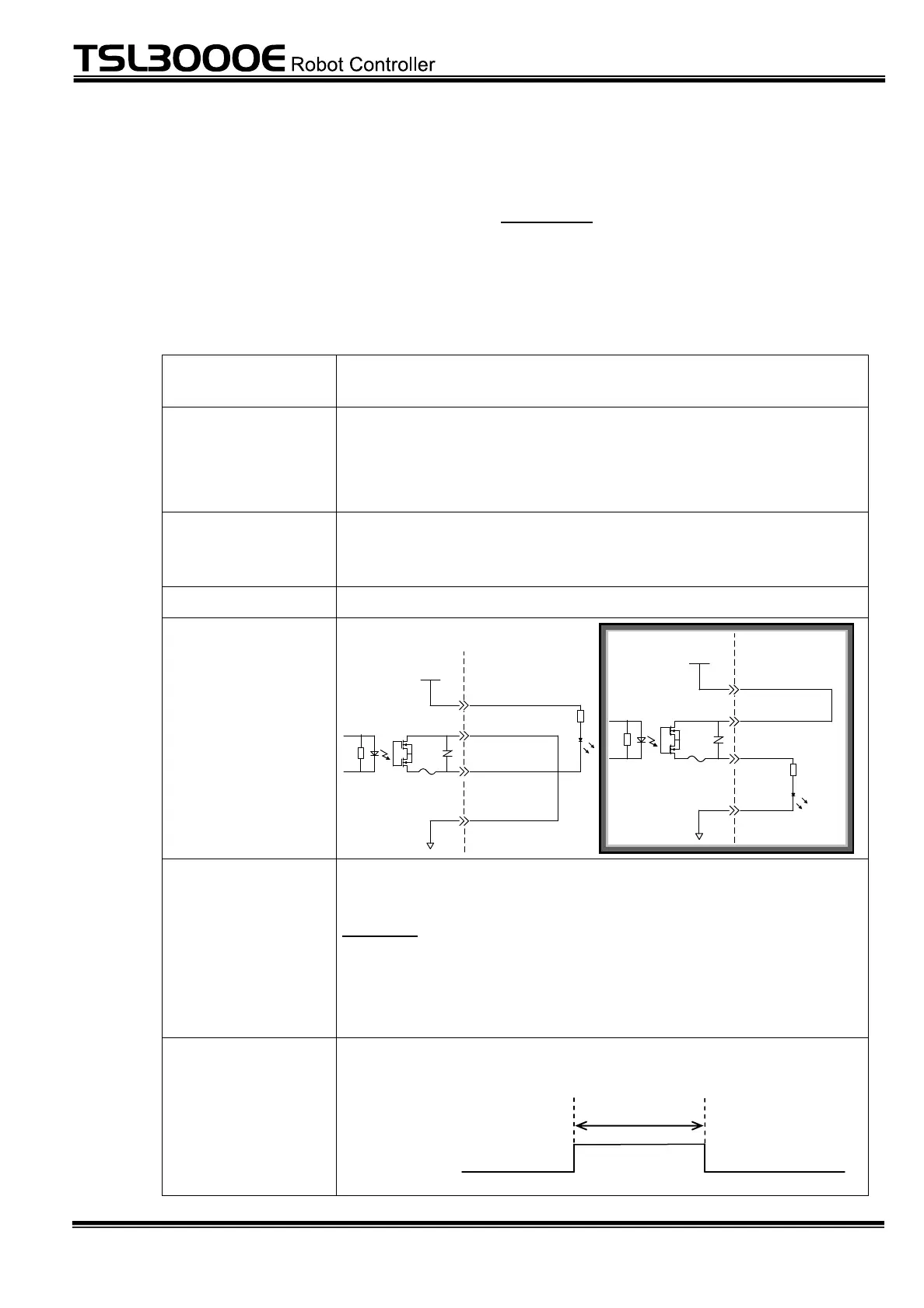
Photo MOS output (bi-direction)
Example of circuit
Output circuit
structure
User side
[P24G(-) common connection]
P24V
P24G
OUTCOM,SYSOUTCOM
DO_*
[Sink type (- common)]
P24V
P24G
OUTCOM,SYSOUTCOM
[Sink type (+ common)]
DO_*
User side
[P24G(+) common connection]
Rated voltage: 24 V DC Rated current: 50 mA (max.)
Caution:
If the current which exceeds the rated output current is
supplied, the output device may be damaged or the printed
board may be burnt. To avoid this, be sure to use within the
rated output current.
When performing pulse output by the PULOUT command, the
output pulse width should be 200 ms or over.
200 ms or over
DO_1 ~ DO_8
 Loading...