– 95 –
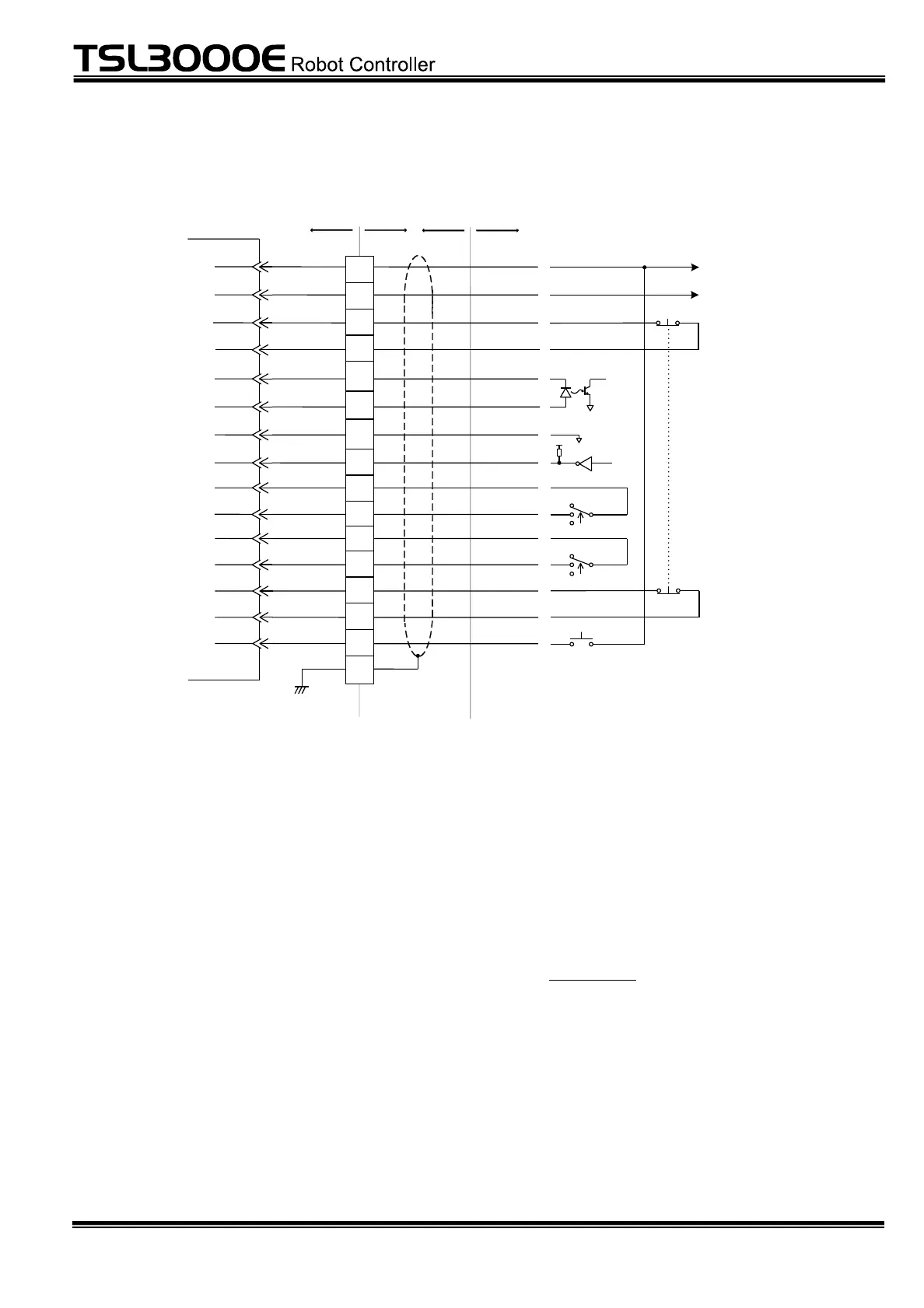
6.2 Connecting Teach Pendant (TP) Cable
Robot controller
TP cable
1
9
2
10
3
11
4
12
5
CASE
P24G
EMS1A
EMS1B
RXDG
RXD
TXDG
TXD
P24V
Connector
(TP)
TP1000
teach pendant
P24V
P24G
EMS1A
EMS1B
RXDG
TXD
TXDG
RXD
13
FG
6
P24V ENABLE2A
14
7
15
8
ENABLE1
P24V
ENABLE2
EMS2A
EMS2B
ENABLE1A
ENABLE1B
ENABLE2B
EMS2A
EMS2B
TP_SVONTP_SVON
Servo ON
Enable 1
Enable 2
Emergency stop contact 2
Emergency stop contact 1
To TP control power circuit
Fig. 6.1 Connection of TP1000 teach pendant I/O signals
The TP cable is a serial I/O signal cable used only for the TP1000 teach pendant
(option). One side of the TP cable is secured to the teach pendant and the other
side has a D-sub 15-pin connector.
Unless the teach pendant is connected, insert the attached dummy plug to
connector TP on the front panel of the controller.
When connecting the teach pendant, remove this dummy plug first. (The attaching
and detaching procedures are the same as in Para. 4.11. For details, see Para.
4.11.)
The dummy plug can be removed while the power of the controller is set ON or OFF.
If the dummy plug is removed while the servo power is turned on, however, the
servo power is turned off automatically. (While the dummy plug or teach pendant
is not connected, safety measures are effected to prevent the servo power from
actuating.)
 Loading...