20
PK114A
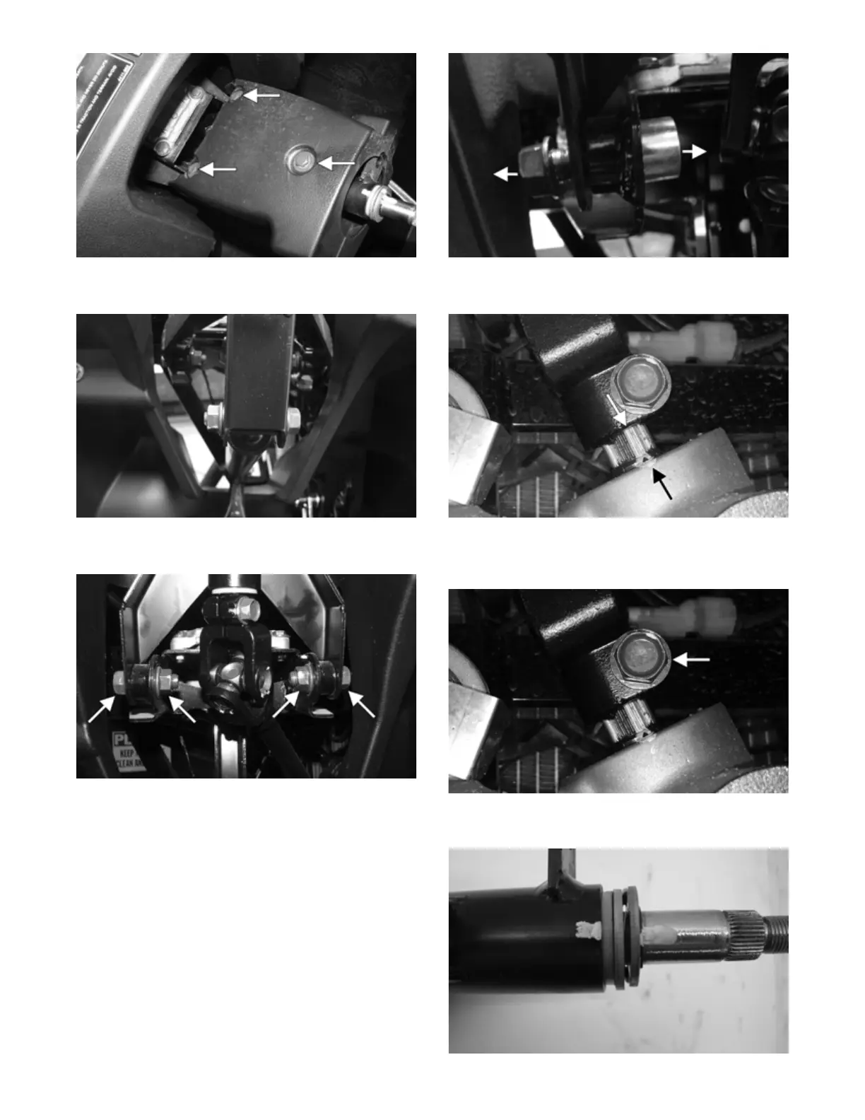
3. Remove the steering shaft lift support cap screw and
nut. Account for the two spacers.
PK115
4. Remove the two nuts securing the cap screws at the
steering shaft housing pivot point.
PK116A
5. Remove the two cap screws with washers (located
toward the left of the steering shaft housing) securing
the dashboard to the frame. Remove the left side
steering shaft housing cap screw first; then remove
the right. Remove the collars from the inside.
PK117A
6. Note the matching alignment marks on the pinion
shaft and rack/pinion housing for assembly purposes.
PK118A
7. Remove the cap screw securing the lower steering
shaft joint to the pinion shaft; then slide the joint free
of the pinion.
PK118B
8. Align the original marks on the upper steering shaft
to the steering column housing.
PK120