21
9. With the marks still aligned from step 8, on the oppo-
site side of the column, match mark the upper inter-
mediate shaft joint to the bottom of the steering
column housing. Remove the cap screw securing the
joint to the upper steering shaft; then remove the
intermediate steering shaft. Account for the two stan-
dard washers and one wave washer.
PK119
INSTALLING STEERING SHAFT
ASSEMBLY
1. Align the marks on the upper steering shaft to the
steering column housing.
PK120
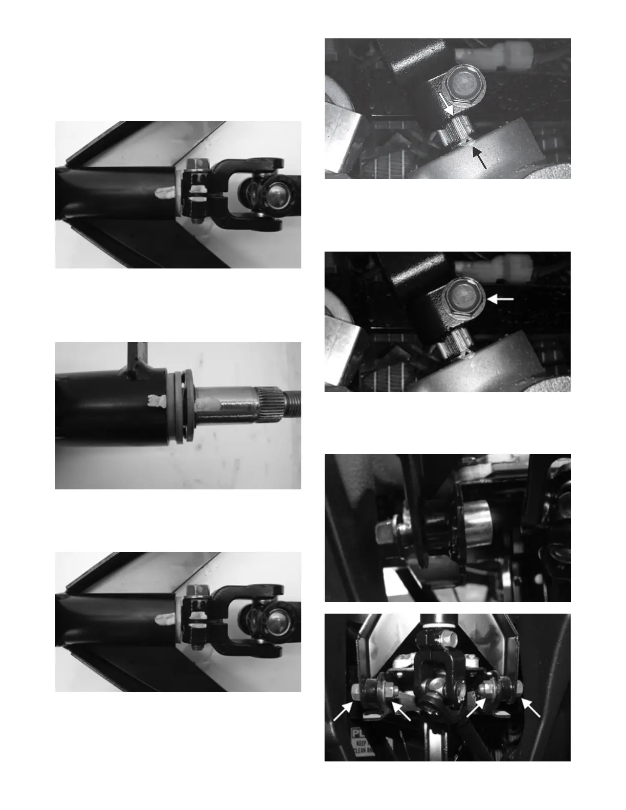
2. Align the gap in the upper intermediate shaft joint to
the previously marked location on the steering col-
umn housing. Secure with the cap screw; then
tighten to 15 ft-lb (20.4 N-m).
PK119
3. Align the match marks on the splined pinion shaft to
the marks on the rack/pinion housing.
PK118A
4. With the marks still aligned from the upper steering
shaft to the steering column housing, place the lower
intermediate shaft joint onto the splined pinion shaft
of the rack/pinion assembly. Tighten the cap screw to
15 ft-lb (20.4 N-m).
PK118B
5. Place the cap screws into position; then install each
spacer into the frame. Install the steering shaft hous-
ing. Secure to the frame with two cap screws and
nuts. Tighten to 23 ft-lb (31.3 N-m).
PK117
PK116A