73
MD1060
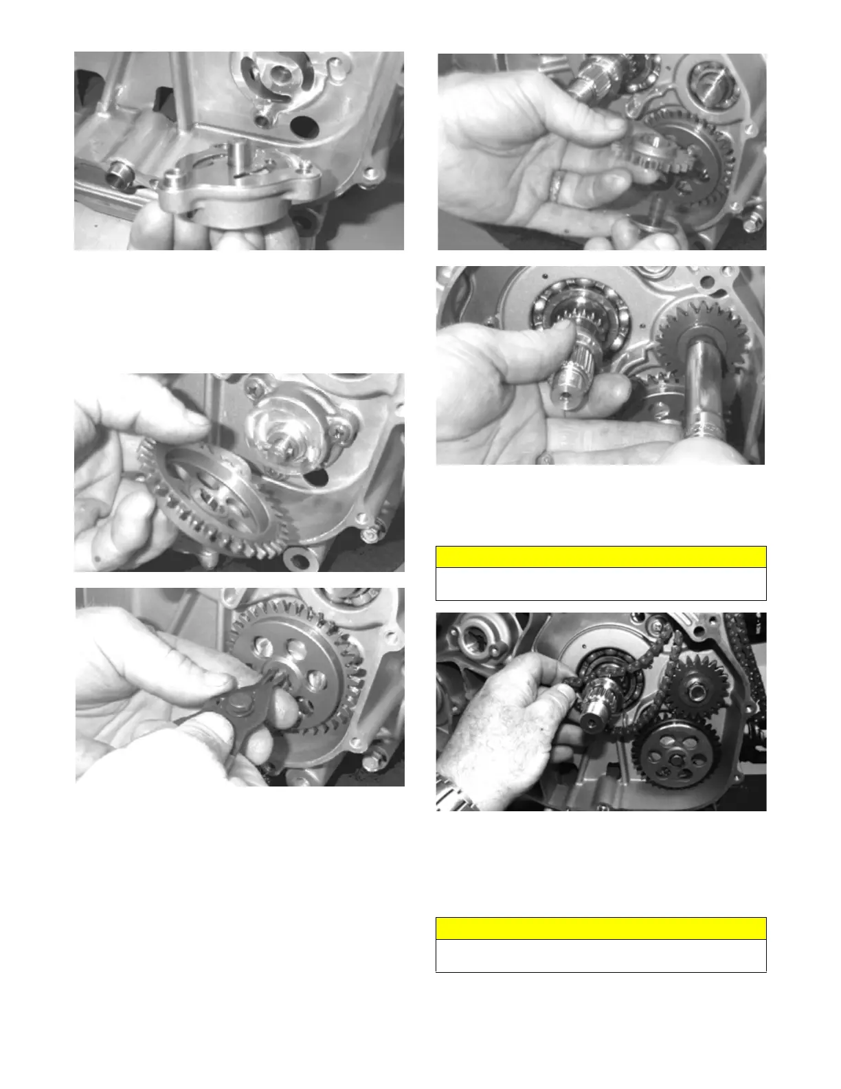
4. Place the thrust washer and drive pin into position on
the oil pump shaft, install the oil pump driven gear
making sure the recessed side of the gear is directed
inward, and secure with a new snap ring.
NOTE: Always use a new snap ring when installing
the oil pump driven gear.
MD1020
MD1019
5. Install the cam chain.
NOTE: Keep tension on the cam chain to avoid
damaging the crankcase boss.
6. Place the pin into position, install the oil pump drive
gear, and tighten the cap screw (coated with red Loc-
tite #271) to 63 ft-lb (85.7 N-m).
MD1017
MD1018
7. Install the cam chain. Engage the cam chain to the
drive teeth on the left side of the crankshaft. Pull the
cam chain up and through the left side crankcase
cover cam chain passage way.
FI630
8. Install the clutch shoe assembly on the crankshaft; then
install the flange nut (left-hand thread) (coated with red
Loctite #271). Tighten to 147 ft-lb (199.3 N-m).
NOTE: The flat side of the flange nut should be
directed toward the clutch shoe.
CAUTION
Do not rotate the crankshaft as damage to the cam
chain will occur.
CAUTION
Care must be taken when installing the flange nut; it has
“left-hand” threads.