32
CVHE-SVX005C-EN
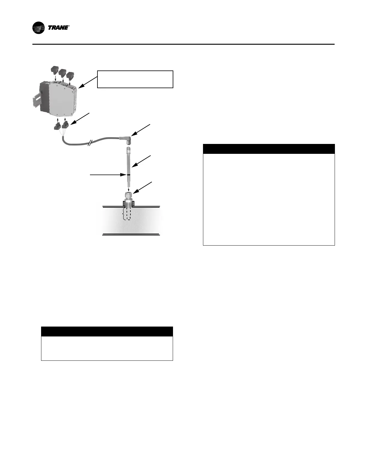
Figure 11. Installation of ifm efector flow detection
controller and sensor
If factory-provided,
located in control panel.
Do NOT insert more than
3.5 in. (8.9 cm) of the
probe length into the pipe.
4
3
2
1
Use a marker to draw a line
on the probe at 3.5 in. (8.9 cm)
from the probe end.
1. Mount the 1/2-in. NPT adapter in a horizontal or vertical
section of pipe. The maximum distance from the control
panel must not exceed 29.5 ft (9 m) (see item labeled
“1” in the preceding figure). Allow at least five pipe
diameters straight run of pipe upstream of the sensor
location, and three pipe diameters straight run of pipe
downstream of the sensor location.
Note: In the case of a horizontal pipe, mounting the
sensor in the side of the pipe is preferred. In the
case of a vertical pipe, mounting the sensor in a
place where the water flows upwards is
preferred.
NOTICE
Overtightening!
Do not exceed torque specifications as it could
result in equipment damage.
2. Insert the flow sensor probe (see item labeled “2” in the
preceding figure) through the 1/2-in. NPT adapter so
that 3 to 3.5 in. (7.6 to 8.9 cm) of the probe’s length
extends into the pipe. Tighten the 1/2-in. NPT adapter
as needed to prevent leakage and keep the probe from
backing out under pressure. Do NOT exceed 40 ft·lb
(54.2 N·m) of torque on the fitting. Sensor damage
can occur if it is overtightened.
Note: When installed, the tip of the ifm efector® sensor
probe must be at least 1 in. (2.54 cm) away from
any pipe wall. Do NOT insert more than 3.5 in.
(8.9 cm) of the probe length into the pipe.
3. Install the Micro DC Cable by inserting it through the
wire openings on the back side of the control panel
(see item labeled “3” in the preceding figure). Install the
supplied Micro DC Cable (29.5 ft [9 m] in length) to the
Flow Probe and hand-tighten the connector nut.
4. Plug the other end of the Micro DC Cable into the Flow
Control Monitor with the Combicon connector (see item
labeled “4” in the preceding figure). Refer to the
following figure for cable wiring.
NOTICE
Do Not Apply Electrical Power to a
Unit in a Vacuum!
Failure to follow instructions below could result in
motor and compressor damage.
Do not apply electrical power to a motor in a
vacuum.
For units with inside-the-delta solid state starters,
disconnect power to unit during evacuation or
when the unit is in a deep vacuum. In addition, on
units with inside-the-delta solid state starters, all
power to the unit must be disconnected prior to
evacuating the unit as line power is directly
applied to the motor terminals 4, 5, and 6.
5. Apply power to the chiller control panel to verify the
Flow Control Monitor has power and the Low Volt
Broken Wire Relay light is NOT lit.
6. Remove all air from the piping circuit prior to adjusting
the low water flow setpoint.
7. Reduce the water flow to the minimum allowable flow
and adjust the Flow setting on the Flow Control Monitor
(see item labeled “7” in the following figure). Adjusting
the “Flow” potentiometer clockwise (+) reduces the flow
setting cutout and adjusting counterclockwise (-)
increases the flow setting cutout.
Note: The “Temp” potentiometer on the ifm efector®
control module has no effect in Trane application.
It is NOT necessary to make adjustments to the
“Temp” potentiometer.
8. After the cutout setting is adjusted, the cutout setpoint
will be indicated with a yellow light on the Flow Control
Monitor LED bar graph display. When the water flows
are higher than the cutout, a green light will indicate
proper flow status. If the flows fall below the cutout
setpoint, a red light will indicate low/no flow status.
Installation: Water Piping