CVHE-SVX005C-EN
63
Terminal Clamps
NOTICE
Use Copper Conductors Only!
Failure to use copper conductors could result in
equipment damage as the equipment was not
designed or qualified to accept other types of
conductors.
Terminal clamps are supplied with the motor terminals to
accommodate either bus bars or standard motor terminal
wire lugs. Terminal clamps provide additional surface area
to minimize the possibility of improper electrical
connections.
Wire Terminal Lugs
NOTICE
Component Damage!
Failure to ensure the power supply wiring and output
to motor wiring are connected to the proper terminals
could cause catastrophic failure of the starter and/or
motor.
Wire terminal lugs must be field supplied.
• Use field-provided, crimp-type wire terminal lugs
properly sized for the application.
Note: Wire size ranges for the starter line and load-side
lugs are listed on the starter submittal drawings
supplied by the starter manufacturer or Trane.
Carefully review the submitted wire lug sizes for
compatibility with the conductor sizes specified
by the electrical engineer or contractor.
• On 4160V and below, a terminal clamp with a
3/8-in. (9.525-mm) bolt is provided on each motor
terminal stud; use the factory-supplied Belleville
washers on the wire lug connections. The following
figure illustrates the junction between a motor terminal
stud and terminal lug.
• Torque for this assembly is 24 ft·lb (32.5 N·m).
• Install but do NOT connect the power leads between
the starter and compressor motor. (These connections
will be completed under supervision of a qualified Trane
service engineer after the pre-start inspection.)
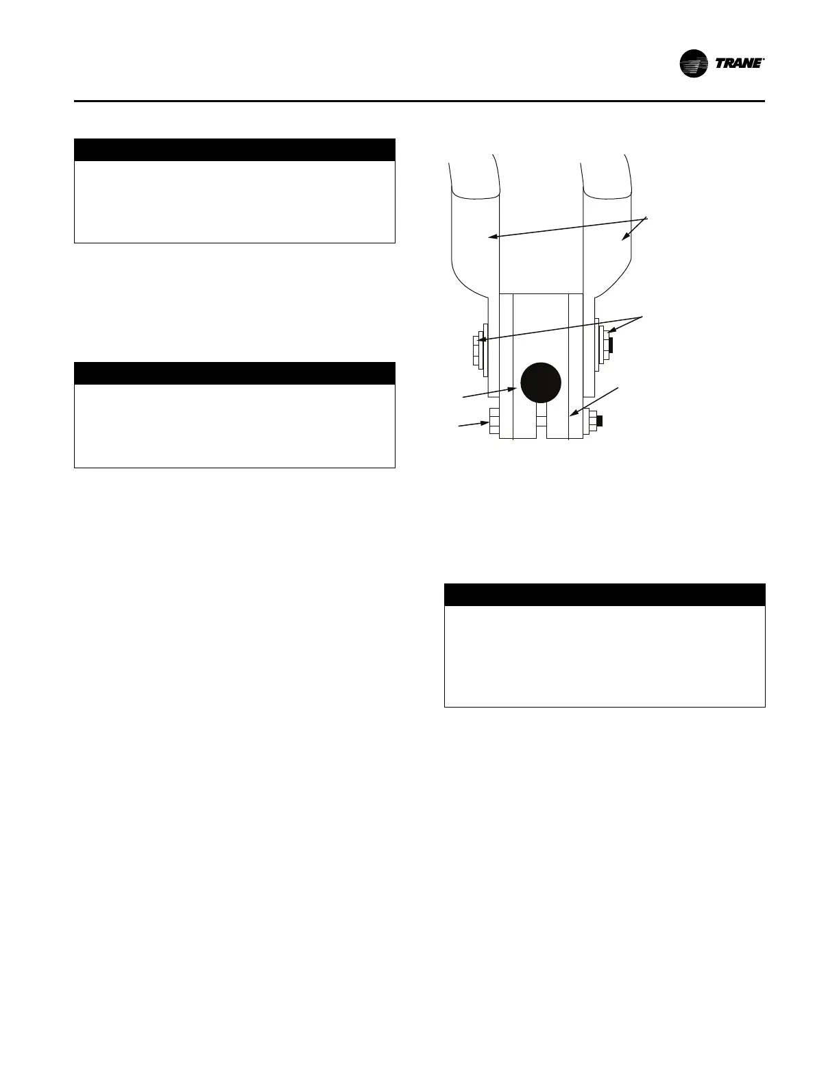
Figure 43. Terminal stud, clamp, and lug assembly
(4160V and below)
1. Belleville washer
2. Terminal lugs
3. Terminal clamp
4. Motor terminal stud
5. 3/8-in. bolt
Bus Bars
NOTICE
Component Damage!
Failure to follow instructions below could cause an
electrical short which could result in component
damage.
Remove debris from inside the CPTR option
enclosure panel before turning the power on.
Bus bars and extra nuts are available as a Trane option.
Install the bus bars between the motor terminals when
using a starter that is:
• A low-voltage Adaptive Frequency™ Drive (AFD)
• Across-the-line
• Primary reactor/resistor
• Autotransformer
• Customer-supplied
Connect T1 to T6, T2 to T4, and T3 to T5.
Note: Bus bars are not needed in medium-voltage or high-
voltage applications since only three terminals are
used in the motor and starter.
When attaching starter leads to 6.6 to 7kV motor terminals,
the 1/2-in.-13 brass jam nuts should be tightened to a
maximum torque of 18 to 22 ft·lb (24.4 to 29.8 N·m).
Power Supply Wiring