CVHE-SVX005C-EN
65
10 to 13.8kV Medium Voltage Motor
WARNING
Hazardous Voltage!
Failure to disconnect power before servicing could
result in death or serious injury.
Disconnect all electric power, including remote
disconnects before servicing. Follow proper lockout/
tagout procedures to ensure the power can not be
inadvertently energized. Verify that no power is
present with a voltmeter.
All electrical circuits shall be treated as energized until all
lockout/tagout procedures are in place and the circuit has
been tested to verify that it is de-energized. The medium-
voltage motor terminal box cover must NOT be removed if
power is present, or if there is a possibility that power may
be present. Working on energized medium-voltage circuits
is not an approved practice for normal HVAC maintenance
or service.
The motor is suitable for remote-mounted across-the-line
(including circuit breaker starting), primary reactor,
autotransformer, or solid-state starting. Refer to the unit
nameplate for motor data including RLA, LRA, etc.
In all cases of non-Trane supplied starters, a disconnecting
means and short-circuit protection must be installed ahead
of the starter, unless they are included as part of the starter.
Note: Trane assumes no responsibility for the design,
documentation, construction, compatibility,
installation, start-up, or long term support of starters
provided by others.
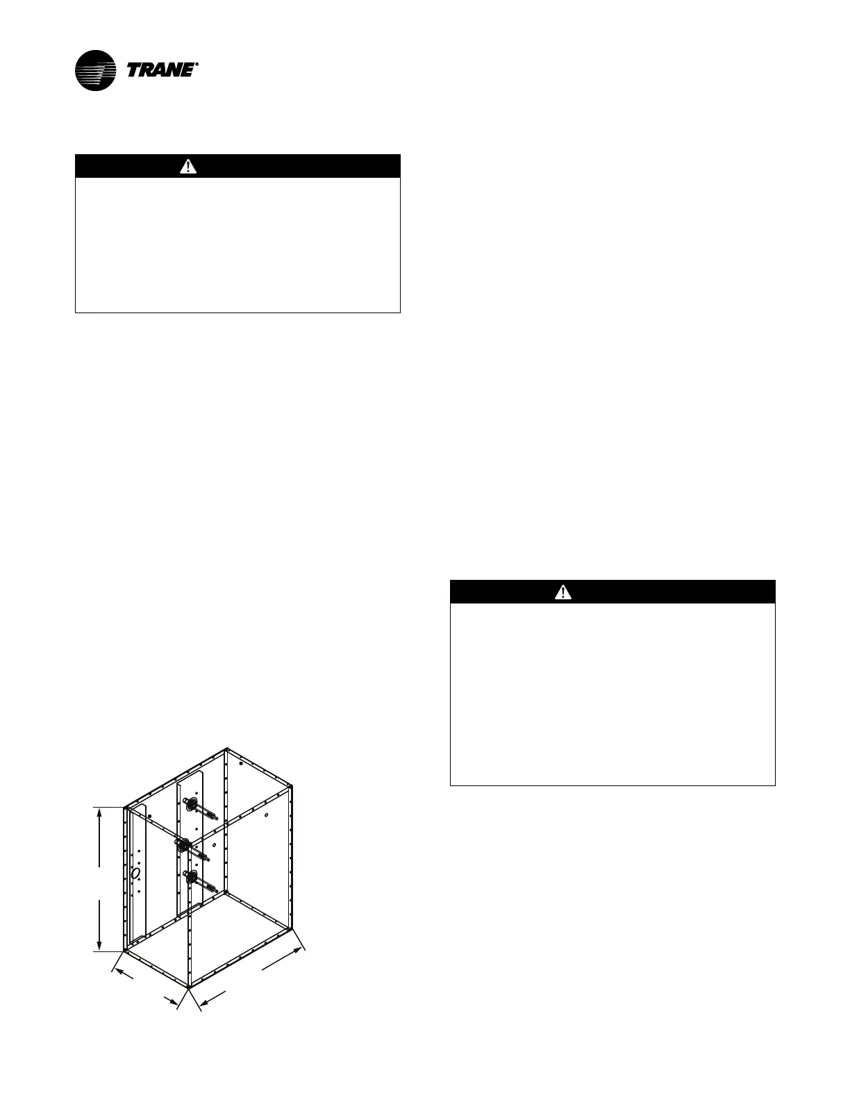
Motor Terminal Box
A large steel motor terminal box is provided to allow for the
field connection of the motor power supply wire to the
motor.
Figure 44. Motor terminal box dimensions, in. (mm)
• Motor terminal box cover-only weight is 55 lb (25 kg).
• Two 7/8-in. (22.225 mm) lifting holes are provided in
the cover.
• Motor terminal box weight without the cover is 215 lb
(97.5 kg).
• Two 3/8-in.–16 weld nuts are provided on the top of the
terminal box to allow the use of properly rated lifting D-
rings if removal is needed for clearance purposes.
Note: If the box is removed for installation purposes,
the motor terminals MUST be protected against
impact or stress damage. Field fabrication of a
cover or guard is required.
• The motor terminal box is large enough to
accommodate the use of stress cones.
• If conduit is applied, a flexible connection of the conduit
to the box should be made to allow for unit
serviceability and for vibration isolation. The cable
should be supported or protected against abrasion and
wear on any edges or surfaces. Cable or conduit
openings can be cut at any location in the box sides,
top, or bottom for cable entry. Always ensure that NO
debris remains in the box after cutting cable entry
holes.
Motor Supply Wiring
WARNING
Proper Field Wiring and Grounding
Required!
Failure to follow code could result in death or serious
injury.
All field wiring MUST be performed by qualified
personnel. Improperly installed and grounded field
wiring poses FIRE and ELECTROCUTION hazards. To
avoid these hazards, you MUST follow requirements
for field wiring installation and grounding as
described in NEC and your local/state/national
electrical codes.
Motor circuit wire sizing by the installer must be made in
accordance with the National Electric Code (NEC) or any
other applicable codes. All wiring to the CenTraVac™
chiller motor must be shielded copper, with insulation rated
to a minimum of 15kV.
Three terminals are provided on the chiller for the
connection of power to the motor from the starter. Power
leads to motors must be in multiples of three, with equal
phase representation in all conduits or wire trays. To limit
the effects of corona or ionization with cables carrying more
than 2000V, Trane requires that the power cable have a
metallic shield, unless the cable is specifically listed or
approved for non-shielded use. If the cable is shielded, the
shielding must be grounded at one end (grounding is
typically done at the starter or supply end).