CVHE-SVX005C-EN
67
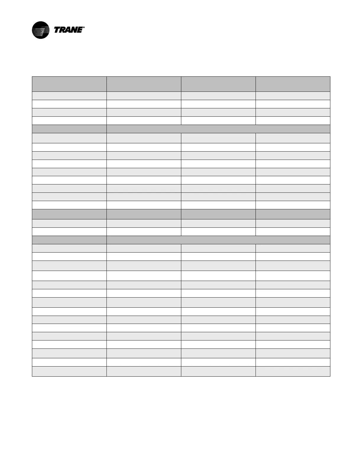
System Control Circuit Wiring (Field Wiring)
Table 19. Unit control panel wiring 120 Vac
Standard Control Circuits: Unit
Control Panel Control Wiring
(120 Vac)
Unit Control Terminations
Input or Output Type
Contacts
Chilled Water Flow Proving Input
(a)
1X1-5 to 1A6-J3-2
Binary Input Normally Open, Closure with Flow
Condenser Water Flow Proving Input
(b)
1X1-6 to 1A6-J2-2
Binary Input Normally Open, Closure with Flow
Chilled Water Pump Relay Output
1A5-J2-4 to 6
Binary Output Normally Open
Condenser Water Pump Relay Output
1A5-J2-1 to 3
Binary Output Normally Open
Optional Control Circuits (120 Vac) Note: Defaults are factory programmed; alternates can be selected at start-up using the service tool.
Alarm Relay MAR (Non-Latching)
Output
1A8-J2-1 to 3
Binary Output Normally Open
Limit Warning Relay Output
1A8-J2-4 to 6
Binary Output Normally Open
Alarm Relay MMR (Latching) Output
1A8-J2-7 to 9
Binary Output Normally Open
Compressor Running Relay Output
1A8-J2-10 to 12
Binary Output Normally Open
Maximum Capacity Relay Output
1A9-J2-1 to 3
Binary Output Normally Open
Head Relief Request Relay Output
1A9-J2-4 to 6
Binary Output Normally Open
Purge Alarm Relay Output
1A9-J2-7 to 9
Binary Output Normally Open
Ice Building Relay Output
1A5-J2-10 to 12
Binary Output Normally Open
Free Cooling Relay Output
1A11-J2-4 to 6
Binary Output Normally Open
Standard Low Voltage Circuits (Less
than 30 Vac)
(c)
Unit Control Panel Terminations
Input or Output Type
Contacts
External Auto Stop Input
1A13-J2-1 to 2
Binary Input Closure Required for Normal Operation
Emergency Stop Input
1A13-J2-3 to 4
Binary Input Closure Required for Normal Operation
Optional Low Voltage Circuits
External Base Loading Enable Input
1A18-J2-1 to 2
Binary Input Normally Open
External Hot Water Control Enable Input
1A18-J2-3 to 4
Binary Input Normally Open
External Ice Building Control Enable
Input
1A19-J2-1 to 2
Binary Input Normally Open
External Free Cooling Input Enable
Input
1A20-J2-1 to 2
Binary Input Normally Open
% RLA Compressor Output
1A15-J2-1 to 3
Analog Output
2–10 Vdc
External Condenser Pressure Output
1A15-J2-4 to 6
Analog Output
2–10 Vdc
Evaporator/Condenser Differential
Pressure Output
1A15-J2-4 to 6
Analog Output
2–10 Vdc
Condenser Head Pressure Control 1A15-J2-4 to 6
Analog Output
0–10 Vdc
External Demand Limit Setpoint Input
1A16-J2-2 to 3
Analog Input
2–10 Vdc, or 4–20 mA
External Chilled Water Setpoint Input
1A16-J2-5 to 6
Analog Input
2–10 Vdc, or 4–20 mA
External Base Loading Setpoint Input
1A17-J2-2 to 3
Analog Input
2–10 Vdc, or 4–20 mA
Generic Refrigerant Monitor Input
1A17-J2-5 to 6
Analog Input
2–10 Vdc, or 4–20 mA
Outdoor Air Temperature Sensor
Inter-processor Communication (IPC)
Bus Connection and Sensor
Communication and Sensor
LonTalk® Module 1K47 LonTalk Comm Link
BACnet® or Modbus™
1A22-ETHERNET 1 OR
1A22-P1(+) to 1A22-P1(-)
Communication to BACnet or Modbus Comm Link
Note: All wiring to be in accordance with National Electrical Code (NEC) and any local codes.
(a)
If the Chilled Water Flow Proving Input is a factory-installed ifm efector flow-sensing device, the secondary field device (recommended with 38°F [3.3°C] and lower leaving
chilled water temperatures) for proof of flow connects from 1X1-5 to 1K26-4 (binary input; normally open, closure with flow). Remove factory jumper when used.
(b)
If the Condenser Water Flow Proving Input is a factory-installed ifm efector flow-sensing device, the secondary (optional) field device for proof of flow connects from 1X1-6 to
1K27-4 (binary input; normally open, closure with flow). Remove factory jumper when used. If the Second Condenser Water Flow Proving Input is a factory-installed ifm
efector flow-sensing device, the secondary (optional) field device for proof of flow connects from 1X1-8 to 1K28-4 (binary input; normally open, closure with flow). Remove
factory jumper when used.
(c)
Standard low-voltage circuits (less than 30 Vac) must be separated from 120 Vac or higher wiring.