58
CVHE-SVX005C-EN
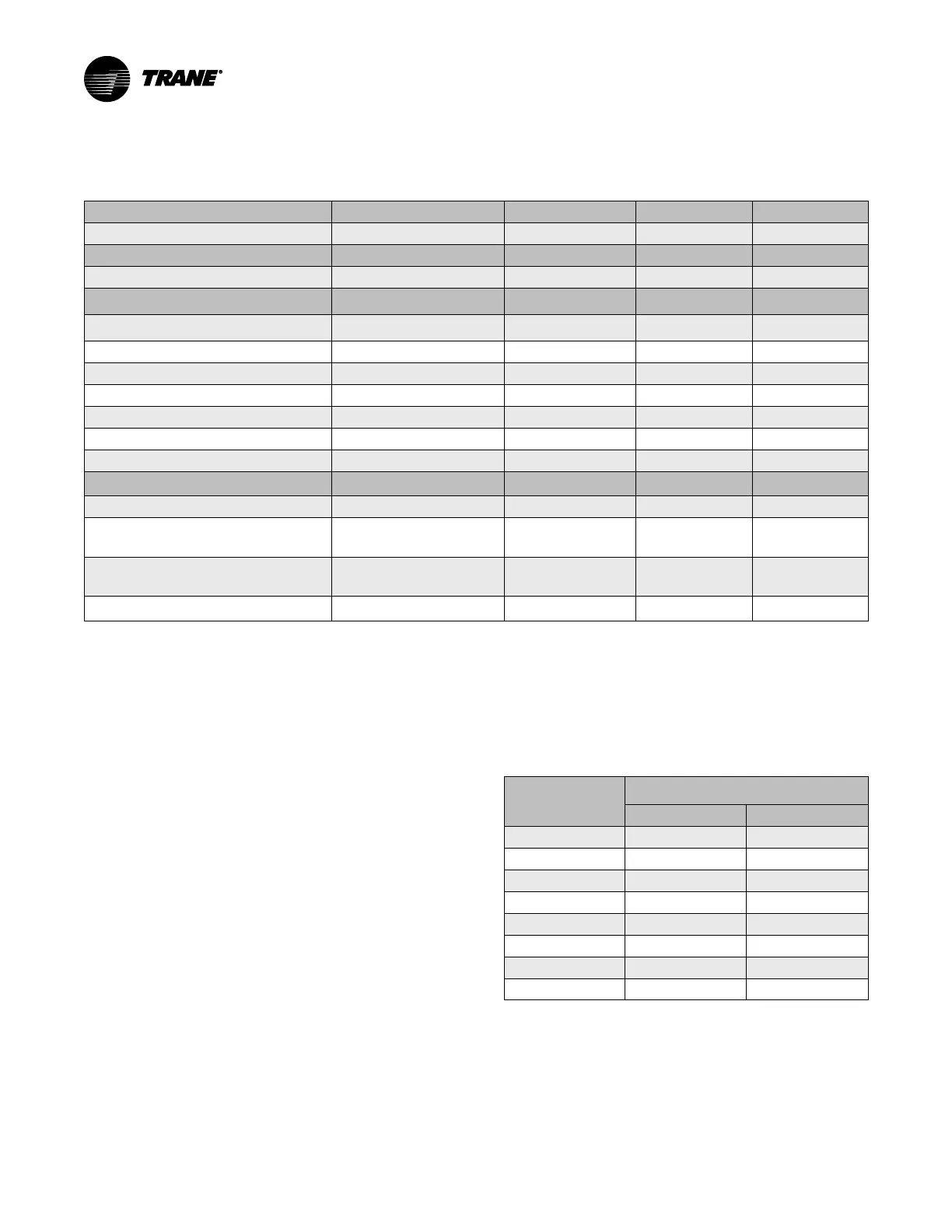
Customer-supplied Remote Starter Wiring
Table 15. Standard customer-supplied remote field wiring requirements
Power Supply Wiring to Starter Panel
Starter Panel Terminals
Starter by Others 3-phase Power Wiring See Starter by Others Schematic
Starter to Motor Power Wiring
Starters Motor
Remote Starter to Chiller Motor Junction Box
T1 through T6 Terminals T1 through T6 Terminals
Starter to Control Panel 120 Vac Control Wiring
Starter Panel Terminals
Unit Control Panel
Terminations
Max Terminal Wire
Size (AWG)
(a)
Minimum Circuit
Ampacity
120 Vac Power Supply (from Starter to Control
Panel)
See Starter by Others Schematic
5X1-1, 5X1-2, 5X1-20 (Ground)
1X1-1, 1X1-12, 1X1-30
(Ground)
8 40
Power from Control Panel 1Q1 5X1-3
1X1-3, 1A23-J6-3
14 20
Interlock Relay Signal
5X1-4 1A23-J10-1 14 20
Start Contactor Signal
5X1-5 1A23-J8-1 14 20
Oil Pump Interlock
5X1-7, 5X1-8 1A7-J2-4, 1A7-J2-2
14 20
Run Contactor Signal
5X1-10 1A23-J6-12 14 20
Transition Complete
5X1-14 1A23-J12-2 14 20
Low Voltage Circuits Less than 30 Vac
Starter Panel Terminals
Unit Control Panel
Terminations
Standard Circuits
Current Transformers (refer to table in “Current
Transformer and Potential Transformer Wire
Sizing,” p. 58) (Required)
(b)
5CT4-white, black
5CT5-white, black
5CT6-white, black
1A23-J7-1,2
1A23-J7-3,4
1A23-J7-5,6
Note: Phasing must be
maintained.
Potential Transformers (Required)
5T17-236,237
5T18-238,239
5T19-240,241
1A23-J5-1,2
1A23-J5-3,4
1A23-J5-5,6
Note: Phasing must be
maintained.
Solid State Stater Fault
(c)
5X1-11
5X1-12
1A24-J2-1
1A24-J2-2
Notes:
1. All wiring to be in accordance with National Electrical Code (NEC) and any local codes.
2. Starter by Others Specification available from your local Trane sales office.
(a)
Wires, lugs, and fuses/breakers are sized based on National Electric Code (NEC) [NFPA 70] and UL 1995.
(b)
Must be separated from 120 Vac and higher wiring.
(c)
Solid State Starter Fault input is used with low- and medium-voltage, customer-supplied solid state starters only.
Current Transformer and
Potential Transformer Wire
Sizing
For customer-supplied starter-to-chiller unit control panel
starter module 1A23; these wires must be separated from
120 Vac or higher wiring.
Table 16. Maximum recommended wire length for
secondary current transformer (CT) leads in
dual CT system
Wire AWG
(a)
Maximum Wire Length
Secondary CT Leads
Feet Meters
8 1362.8 415.5
10 856.9 261.2
12 538.9 164.3
14 338.9 103.3
16 213.1 65.0
17 169.1 51.5
18 134.1 40.9
20 84.3 25.7
Notes:
1. Wire length is for copper conductors only.
2. Wire length is total one-way distance that the CT can be from the starter
module.
(a)
Wires, lugs, and fuses/breakers are sized based on National Electric Code
(NEC) [NFPA 70] and UL 1995.