CVHE-SVX005C-EN
33
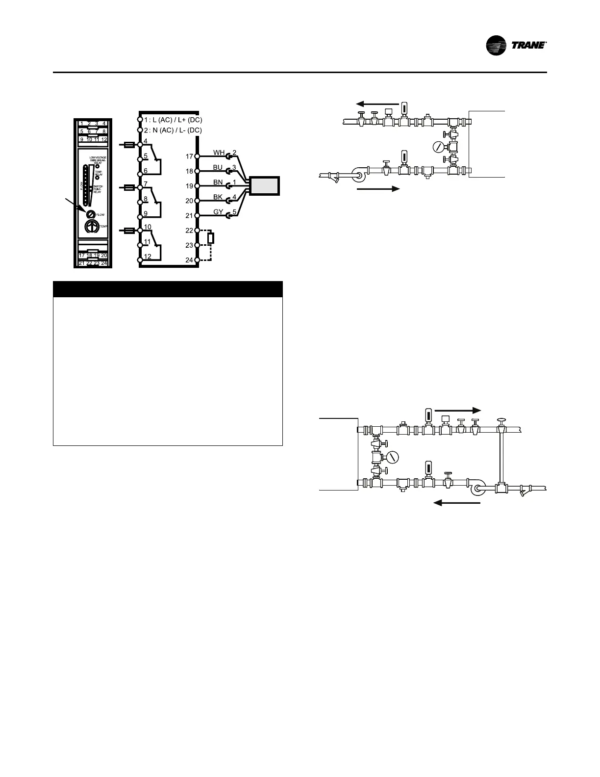
Figure 12. ifm efector® flow sensing device terminal
connection
NOTICE
Proof of Flow Switch!
Failure to provide flow switches or jumping-out of
switches could result in severe equipment damage.
Evaporator and condenser water circuits require
proof of flow switches.
• Failure to include the proof of flow devices and/or
jumping out these devices could cause the unit to
stop on a secondary level of protection.
• Frequent cycling on these higher level diagnostic
devices could cause excessive thermal and pressure
cycling of unit components (O-rings, gaskets,
sensors, motors, controls, etc.) and/or freeze damage,
resulting in premature failure of the chiller.
Evaporator and condenser proof of flow switches (either
flow or Delta-P) are required as shown on wiring diagrams.
These switches are used with control logic to confirm flow
prior to starting a unit and to stop a running unit if flow is
lost. For troubleshooting, a viewable diagnostic is
generated if a proof of flow switch does not close when flow
is required.
Evaporator and Condenser
Water Piping
The following two figures illustrate the recommended
(typical) water piping arrangements for the evaporator and
condenser.
Figure 13. Typical evaporator water piping circuit
4
45
53
3
7
2
2 1
9
6
2
2
8
Outlet
Inlet
1. Balancing valve.
2. Gate (Isolation) valve or ball valve.
3. Thermometer (if field supplied).
4. Waterbox nozzle connection.
5. Drain, vent, and anode.
6. Strainer.
7. Chilled water flow switch (5S1). Flow switch 5S1 may
be installed in either the entering or leaving leg of the
chilled water circuit.
8. Pump.
9. Pressure gauge. It is recommended to pipe the gauge
between entering and leaving pipes. A shutoff valve on
each side of the gauge allows the operator to read
either entering or leaving water pressure.
Figure 14. Typical condenser water piping circuits
1 2
3
4 5
6
7 8
92
3
4 5
2
2
10
Outlet
Inlet
1. Balancing valve.
2. Gate (isolation) valve or ball valve.
3. Thermometer (if field supplied).
4. Waterbox nozzle connection.
5. Drain, vent, and anode.
6. Strainer.
7. Condenser water flow switch (5S2). Flow switch 5S2
may be installed in either the entering or leaving leg of
the chilled water circuit.
8. Three-way valve (optional).
9. Condenser water pump.
10. Pressure gauge. It is recommended to pipe a single
gauge between entering and leaving pipes.
Installation: Water Piping
 Loading...


