CVHE-SVX005C-EN
71
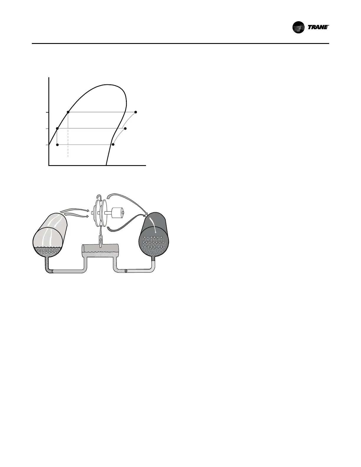
economizer, passing through another orifice plate and into
the evaporator.
Figure 47. Pressure enthalpy curve
Condenser
Economizer
Evaporator
Compressor
Second Stage
Compressor
First Stage
6
5
4
3
1 2
Pressure
Enthalpy
P
3
P
1
P
2
Figure 48. Refrigerant flow, 2-stage
Oil and Refrigerant Pump
Compressor Lubrication System
A schematic diagram of the compressor lubrication system
is illustrated in the following figure. Oil is pumped from the
oil tank (by a pump and motor located within the tank)
through an oil pressure regulating valve designed to
maintain a net oil pressure of 18 to 22 psid (124.1 to 151.7
kPaD). It is then filtered and sent to the oil cooler located in
the economizer and on to the compressor motor bearings.
From the bearings, the oil drains back to the manifold and
separator under the motor and then on to the oil tank.
Operating Principles