CVHE-SVX005C-EN
47
Insulation
Unit Insulation Requirements
Factory-installed insulation is available as an option for all
units. Factory installation does NOT include insulation of
the chiller feet; if required, insulation for chiller feet is
provided by others. In applications where the chiller is not
factory-insulated, install insulation over the areas outlined
and highlighted with dashed lines as shown in the figure in
“Factory-applied Insulation,” p. 47.
Insulate all 1/4-in. (6.35-mm) eductor lines, one from the
suction cover and one from the evaporator, to prevent
sweating.
The quantities of insulation required based on unit size and
insulation thickness are listed in the following table.
Insulation thickness is determined at normal design
conditions which are:
• Standard comfort-cooling leaving chilled water
temperature
• 85°F (29.4°C) dry bulb ambient temperature
• 75 percent relative humidity
Operation outside of normal design conditions as defined in
this section may require additional insulation; contact Trane
for further review.
Note: If the unit is not factory-insulated, install insulation
around the evaporator bulbwells and ensure that the
bulbwells and connections for the waterbox drains
and vents are still accessible after insulation is
applied. The sensor modules (Low Level Intelligent
Devices [LLIDs]) and interconnecting four-wire cable
inter-processor communication (IPC) bus must be
raised up above the field-installed insulation. Secure
the IPC bus to the insulation top/outer surface after
insulation is completed.
Important: Do NOT insulate the motor housing, unit wiring,
or sensor modules.
NOTICE
Equipment Damage!
Failure to remove the strain relief with the sensor
could result in equipment damage.
Do NOT attempt to pull sensor bulb through the strain
relief; always remove the entire strain relief with the
sensor.
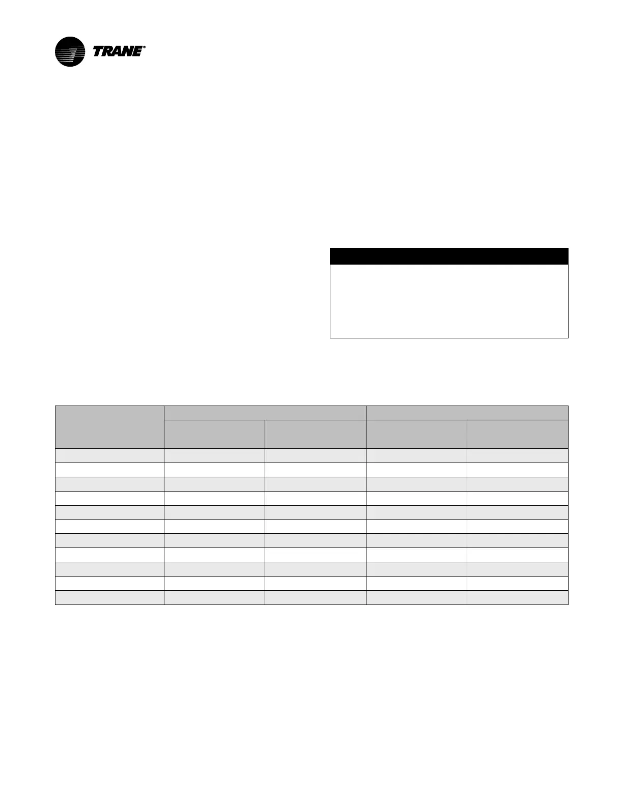
Table 13. Evaporator insulation requirements
EVSZ
(a)
Standard Unit
Free Cooling
3/4 in. (19.05 mm)
(a)
Insulation(Square Feet)
3/8 in. (9.525 mm)
Insulation
(b)
(Square Feet)
3/4-in. (19.05 mm)
Insulation
(a)
(Square Feet)
3/8 in. (9.525 mm)
Insulation
(b)
(Square Feet)
032 Short 337 52 347 74
032 Long
365 52 377 74
050 Short 385 63 398 72
050 Long
420 63 436 72
080 Short 505 84 515 97
080 Long
553 84 566 97
142 Medium 555 98 555 133
142 Long
578 98 578 133
142 Extended 603 104 629 133
210 Long
700 98 710 133
250 Extended 770 97 780 133
Note: Chillers equipped with refrigerant pumps are NOT insulated on the motor or refrigerant drain lines.
(a)
3/4-in. (19.05-mm) sheet insulation is installed on the evaporator, evaporator waterboxes, suction elbow, and suction cover.
(b)
3/8-in. (9.525-mm) sheet insulation is installed on all economizers. All liquid lines and other pipes require the use of 1/2-in. (12.7-mm) pipe insulation or 3/8-in. (9.525-mm)
sheet insulation. Copper oil eductor tube lines require pipe insulation.
Insulation Thickness
Requirements
Factory-applied Insulation
All low-temperature surfaces are covered with 3/4 in.
(19.05 mm) Armaflex® II or equal (thermal conductivity =
0.28 Btu/h-ft
2
[1.59 W/m
2
-K]), including the evaporator,
waterboxes, and suction elbow. The economizer and motor
cooling lines are insulated with 3/8 in. (9.525 mm) and 1/2
in. (12.7 mm) insulation, respectively.
The insulation is Armaflex® or equivalent closed cell
elastomeric insulation to prevent the formation of
condensation up to a dew point rating of 74°F (23.3°C), K =
0.25. Chillers in high humidity areas or ice storage, low
leaving water temperature (less than 36°F [2.2°C] chilled