70
CVHE-SVX005C-EN
Operating Principles
General Requirements
Operation and maintenance information are covered in this
section. This includes both 50 and 60 Hz centrifugal chillers
equipped with the Tracer
®
Symbio™ 800 control system.
This information pertains to all chiller types unless
differences exist, in which case the sections are listed by
chiller type as applicable and described separately. By
carefully reviewing this information and following the
instructions given, the owner or operator can successfully
operate and maintain the chiller. If mechanical problems do
occur, however, contact a Trane service technician to
ensure proper diagnosis and repair of the unit.
Important: Although CenTraVac™ chillers can operate
through surge, it is NOT recommended to
operate them through repeated surges over
long durations. If repeated surges of long
durations occur, contact your Trane Service
Agency to resolve the issue.
Cooling Cycle
When in the cooling mode, liquid refrigerant is distributed
along the length of the evaporator and sprayed through
small holes in a distributor (i.e., running the entire length of
the shell) to uniformly coat each evaporator tube. Here, the
liquid refrigerant absorbs enough heat from the system
water circulating through the evaporator tubes to vaporize.
The gaseous refrigerant is then drawn through the
eliminators (which remove droplets of liquid refrigerant from
the gas) and the first-stage variable inlet guide vanes, and
into the first-stage impeller.
CVHE and CVHG 3-Stage Compressor
Compressed gas from the first-stage impeller flows through
the fixed, second-stage inlet vanes and into the second-
stage impeller. Here, the refrigerant gas is again
compressed, and then discharged through the third-stage
variable guide vanes and into the third-stage impeller. After
the gas is compressed a third time, it is discharged into the
condenser. Baffles within the condenser shell distribute the
compressed refrigerant gas evenly across the condenser
tube bundle. Cooling tower water circulated through the
condenser tubes absorbs heat from the refrigerant, causing
it to condense. The liquid refrigerant then passes through
an orifice plate and into the economizer.
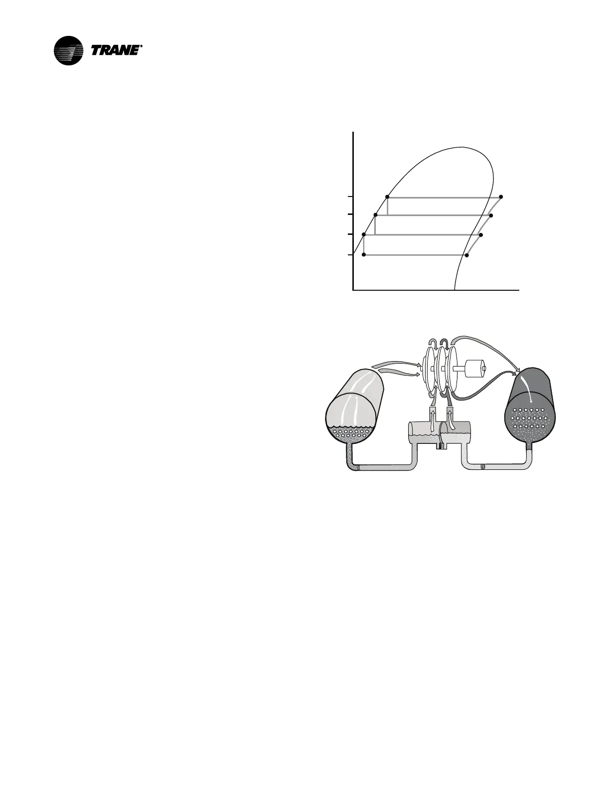
The economizer reduces the energy requirements of the
refrigerant cycle by eliminating the need to pass all
gaseous refrigerant through three stages of compression
(refer to the following figure). Notice that some of the liquid
refrigerant flashes to a gas because of the pressure drop
created by the orifice plates, thus further cooling the liquid
refrigerant. This flash gas is then drawn directly from the
first and second stages of the economizer into the third-
and second-stage impellers of the compressor,
respectively. All remaining liquid refrigerant flows through
another orifice plate to the evaporator.
Figure 45. Pressure enthalpy curve, 3-stage
Condenser
High Side Economizer
Low Side Economizer
Evaporator
Compressor
Third Stage
Compressor
Second Stage
Compressor
First Stage
6
5
7
4
8
3
1 2
Pressure
Enthalpy
P
4
P
3
P
1
P
2
Figure 46. Refrigerant flow, 3-stage
CVHF 2-Stage Compressor
Compressed gas from the first-stage impeller is discharged
through the second-stage variable guide vanes and into the
second-stage impeller. Here, the refrigerant gas is again
compressed, and then discharged into the condenser.
Baffles within the condenser shell distribute the
compressed refrigerant gas evenly across the condenser
tube bundle. Cooling tower water circulated through the
condenser tubes absorbs heat from the refrigerant, causing
it to condense. The liquid refrigerant then flows out of the
bottom of the condenser, passing through an orifice plate
and into the economizer.
The economizer reduces the energy requirements of the
refrigerant cycle by eliminating the need to pass all
gaseous refrigerant through both stages of compression
(refer to the following figure). Notice that some of the liquid
refrigerant flashes to a gas because of the pressure drop
created by the orifice plate, thus further cooling the liquid
refrigerant. This flash gas is then drawn directly from the
economizer into the second-stage impellers of the
compressor. All remaining liquid refrigerant flows out of the