CVHE-SVX005C-EN
61
Notes:
• Verify PFCC voltage rating is greater than or
equal to the compressor voltage rating stamped
on the unit nameplate.
• Refer to the wiring diagrams that shipped with
the unit for specific PFCC wiring information.
NOTICE
Motor Damage!
Failure to wire PFCCs into the starter correctly could
cause misapplication of these capacitors and result in
a loss of motor overload protection and subsequently
cause motor damage.
PFCCs must be wired one of two ways as shown as
explained in the following figures and accompanying
text (Option 1 and Option 2).
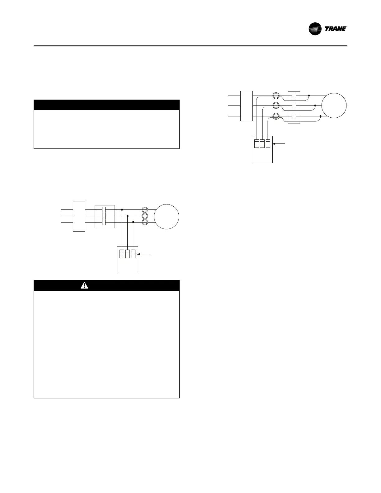
Figure 39. Option 1 — PFCCs installed downstream
of starter contactor, upstream of current transformers
Power
Circuit
1
2
3
Fused
Disconnect
or Suitable
Breaker
Motor Starter
Contactor
Motor
Current
Transformer
Fuses
Enclosed
3-phase
Capacitor
Unit
WARNING
Hazardous Voltage w/Capacitors!
Failure to disconnect power and discharge capacitors
before servicing could result in death or serious
injury.
Disconnect all electric power, including remote
disconnects and discharge all motor start/run
capacitors before servicing. Follow proper lockout/
tagout procedures to ensure the power cannot be
inadvertently energized. For variable frequency drives
or other energy storing components provided by
Trane or others, refer to the appropriate
manufacturer’s literature for allowable waiting periods
for discharge of capacitors. Verify with a CAT III or IV
voltmeter rated per NFPA 70E that all capacitors have
discharged.
Simultaneously disconnect capacitors and load from line
power. If the capacitors are not switched offline when the
load is disconnected, they continue to add capacitance to
the electrical distribution system. A leading power factor
and too much capacitance may eventually develop. This
overprotection causes poor voltage regulation (i.e., voltage
is high when the circuit is unloaded, then drops as loads
are added).
Figure 40. Option 2—PFCC wires routed through
current transformers
Power
Circuit
1
2
3
Fused
Disconnect
or Suitable
Breaker
Motor Starter
Contactor
Motor
Current
Transformer
Fuses
Enclosed
3-phase
Capacitor
Unit
Size motor overload protection to account for capacitor-
supplied current. Overloads are typically set to measure
the total current drawn by the motor. When PFCCs are
used, they become the source of part of that current. If the
current they provide is not registered by the overload
protectors, potentially damaging amperage can reach the
motor. The simplest way to ensure that the overloads
detect all current supplied to the motor is to position the
PFCCs upstream of the current transformers as shown in
the preceding figure (Option 1). If the capacitor connection
points are downstream of the current transformers, route
the PFCC leads through the current transformers as shown
in the preceding figure (Option 2). This ensures that the
overloads register both line and capacitor-supplied current.
Interconnecting Wiring
Typical equipment room conduit layouts with and without
unit-mounted starters are shown in the following two
figures.
Important: The interconnecting wiring between the starter
panel, compressor, and control panel is
factory-installed with unit-mounted starters.
However, when a remote-mounted starter is
used, the interconnecting wiring must be field-
installed.
Note: Refer to starter submittal drawing for location of
incoming wiring to the starter.
Power Supply Wiring