36
CVHE-SVX005C-EN
Notes:
• Refer to the coupling manufacturer’s guidelines
for specific information concerning proper
piping system design and construction methods
for grooved water piping systems.
• Flexible coupling gaskets require proper
lubrication before installation to provide a good
seal. Refer to the coupling manufacturer’s
guidelines for proper lubricant type and
application.
Flange-connection Adapters
NOTICE
Never Weld to Cast Boxes!
Welding to cast boxes will result in equipment
damage.
Adapters must be used to convert flanges.
When flat-face flange connections are specified, flange-to-
groove adapters are provided (Victaulic® Style 741 for
150 psig [1034.2 kPaG] systems; Style 743 for 300 psig
[2068.4 kPaG] systems). The adapters are shipped
screwed to one of the chiller end-supports. Adapter
descriptions are given in the tables in “Victaulic Gasket
Installation,” p. 36. The flange adapters provide a direct,
rigid connection of flanged components to the grooved-pipe
chiller waterbox connections.
Figure 17. Typical shipping location for flange
In this case, the use of flexible type connectors (i.e.,
braided steel, elastomeric arch, etc.) are recommended to
attenuate vibration and prevent stress at the waterbox
connections. Flange adapters are not provided for CVHE,
CVHF, or CVHG CenTraVac™ chillers with 300 psig
(2068.4 kPaG) waterboxes that have 14 in. (355.6 mm) and
16 in. (406.4 mm) piping connections.
All flange-to-flange assembly screws must be provided by
the installer. Hex head screw sizes and number required
are included in the tables in “Victaulic Gasket
Installation,” p. 36. The four draw-bolts needed for the
14 in. (355.6 mm) and 16 in. (406.4 mm) Style 741
(150 psig [1034.2 kPaG]) adapters are provided. The
Style 741 (150 psig [1034.2 kPaG]) flange adapter requires
a smooth, hard surface for a good seal.
Connection to other type flange faces (i.e., raised, serrated,
rubber, etc.) requires the use of a flange washer between
the faces. Refer to the flange adapter manufacturer’s
guidelines for specific information.
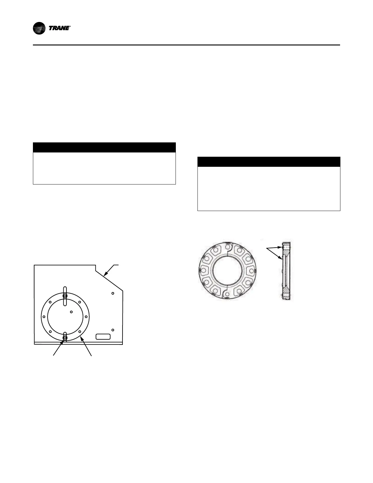
The Style 743 (300 psig [2068.4 kPaG]) flange adapters
are designed to mate with raised-face flanges. They can be
used with flat-faced flanges, but only if the raised
projections on the outside face of the adapter are removed;
refer to the following figure. The flange-adapter gasket
must be placed with the color-coded lip on the pipe and the
other lip facing the mating flange.
NOTICE
Piping Connection Leaks!
Failure to provide effective seal could result in
equipment or property-only damage.
To provide effective seal, gasket contact surfaces of
adapter must be free of gouges, undulations or
deformities.
Figure 18. Modifying 300 psig (2068.4 kPaG) flange
adaptors for flat-faced flange application
Remove to mate
to flat-faced
flanges
Victaulic Gasket Installation
1. Inspect supplied gasket to be certain it is suited for
intended service (code identifies gasket grade). Apply a
thin coat of silicone lubricant to gasket tips and outside
of gasket.
2. Install gasket, placing gasket over pipe end and making
sure gasket lip does not overhang pipe end. Refer to
the following figure for gasket configuration.
3. Align and bring two pipe ends together and slide gasket
into position centered between the grooves on each
pipe. No portion of the gasket should extend into the
groove on either pipe.
4. Open fully and place hinged Victaulic® flange around
the grooved pipe end with the circular key section
locating into the groove.
5. Insert a standard hex head screw through the mating
holes of the Victaulic® flange to secure the flange firmly
in the groove.
Installation: Water Piping