CVHE-SVX005C-EN
31
Strainers
NOTICE
Water Borne Debris!
To prevent components damage, pipe strainers must
be installed in the water supplies to protect
components from water borne debris. Trane is not
responsible for equipment-only-damage caused by
water borne debris.
Install a strainer in the entering side of each piping circuit to
avoid possible tube plugging in the chiller with debris.
Required Flow-Sensing Devices
Use flow paddle switches (refer to “Paddle Switches,” p.
31), differential pressure switches, or ifm efector® flow
detection controllers and sensors (refer to “Water Flow
Detection Controller and Sensor ,” p. 31) in conjunction
with the pump interlocks to verify evaporator and
condenser water flows.
To ensure adequate chiller flow protection, wire the chiller
water and condenser water proof of flow devices per the
as-built schematics and submittal, and in accordance with
associated notes.
Unless stated otherwise, all flow sensing devices must be
field supplied. Be sure to follow the manufacturer’s
recommendations for device selection and installation.
Also, review the following general flow switch installation
guidelines.
Paddle Switches
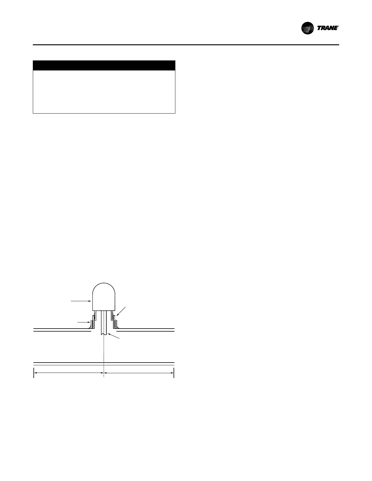
Figure 10. Flow paddle switch installation
1. Flow switch body
2. One (1) pipe size larger bushing to avoid paddle
interference
3. Pipe coupling
4. Flow switch paddle
5. Five (5) pipe diameters (no turns or fittings)
Paddle switch installation:
1. Mount the flow paddle switch upright in horizontal
section of pipe. Allow at least five pipe diameters of
straight, horizontal run on each side of the switch.
Whenever possible, avoid locations adjacent to elbows,
orifices, and valves.
2. To ensure that the flow switch operates as designed,
adjust the length of the flow switch paddle to
compensate for the pipe diameter and the height of the
coupling used to install the switch.
3. Install the flow switch using a coupling that is large
enough to allow the insertion of a bushing one pipe
diameter larger than the flow switch base as shown in
the preceding figure. This will prevent interference with
the flow switch paddle.
4. Verify that the direction-of-flow arrow on the switch
points in the same direction as actual water flow
through the piping circuit.
5. Remove all air from the piping circuit to prevent
possible flow switch fluttering.
6. Adjust the flow switch to open when water flow is less
than normal.
Water Flow Detection Controller and
Sensor
Important: Before installing the ifm efector® flow detection
controller and sensor, use a marker to draw a
line on the probe at 3.5 in. (8.9 cm) from the
end of the probe. Do NOT insert more than 3.5
in. (8.9 cm) of the probe length into the pipe.
Refer to the following figure.
Installation: Water Piping