42
CVHE-SVX005C-EN
NOTICE
Proper Refrigerant Vent Line
Termination!
Failure to properly terminate a refrigerant vent line
could result in equipment damage.
Improperly terminating a refrigerant vent line could
allow rain to enter the line. Accumulated rainwater
could cause the relief device to malfunction; or, in the
case of a rupture disk, the rainwater pressure could
cause the disk to rupture, allowing water to enter the
chiller.
• Route the vent-line piping so that it discharges
outdoors in an area that will not spray refrigerant on
anyone. Position the vent-line discharge at least 15 ft
(4.6 m) above grade level and at least 20 ft (6.1 m) from
any building opening. Provide a vent-line termination
that cannot be blocked by debris or accumulate
rainwater.
• Provide a drip leg on the vent line (refer to the following
figure [arrangement for rupture disk relief piping]).
Provide a standard 1/4-in. FL x 1/4-in. NPT, capped
refrigerant service valve to facilitate liquid removal.
NOTICE
Equipment Damage!
Failure to follow instructions below could result in
equipment damage.
All vent lines must be equipped with a drip leg of
sufficient volume to hold the expected accumulation
of water and/or refrigerant. The drip leg must be
drained periodically to assure that it does not
overflow and allow fluid to flow into the horizontal
portion of the vent line. Trane assumes no
responsibility for equipment damage caused by
insufficient drainage of drip leg.
• Consult local regulations and codes for any additional
relief line requirements and refer to appropriate
refrigerant handling guidelines. For chillers with R-123
refrigerant, refer to R-123 Low-Pressure Refrigerant
Handling Guidelines Conservation and Safe Handling
of R-123 Refrigerant in Trane Chillers for Service
Technicians Installation, Operation, and Maintenance
(CTV-SVX05*-EN). For chillers with R-514A refrigerant,
refer to R-514A Low-Pressure Refrigerant Handling
Guidelines Conservation and Safe Handling of R-514A
Refrigerant in Trane Chillers for Service Technicians
Installation, Operation, and Maintenance (CTV-
SVX008*-EN).
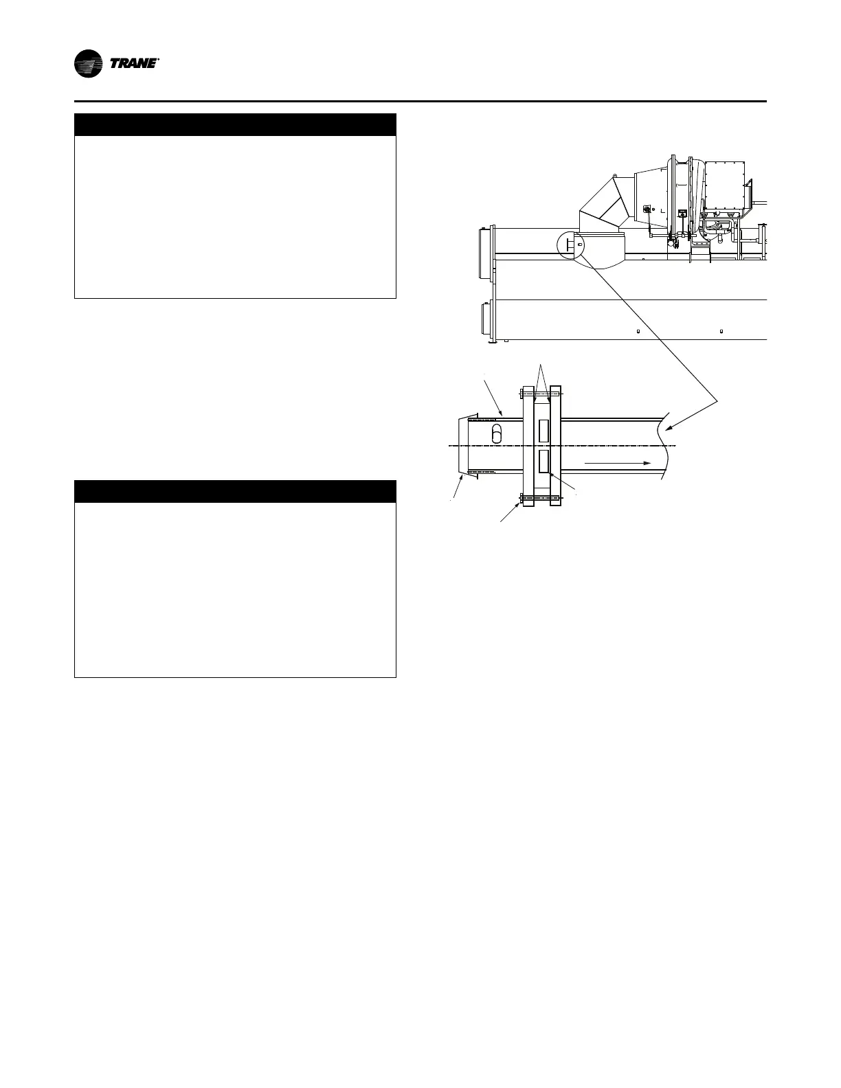
Figure 24. Rupture disk location and cross section of
rupture disk
Outside pipe
assembly
Gasket
Cap
Bolt
Rupture disk
Suction connection
Note: Pipe connection is 3 in. (76.2 mm) NPT, except 250E
evaporator/250L condenser units with heat recovery
which have a 4 in. (101.6 mm) NPT pipe connection.
Vent Piping