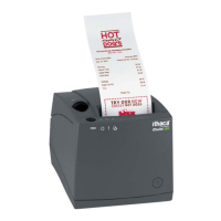
Specifications and Requirements iTherm
®
280 Programmer’s Guide
28-04430 Rev K Page 23
Communications Interface
Parallel Interface
Your printer features two parallel interfaces:
An IEEE 1284-A 25-pin, D-shell connector, with pin-outs that interface to a
standard IBM PC parallel printer interface with a one-to-one cable.
An IEEE 1284-B, which is a standard Centronics 36-pin connector.
Both interface cards provide a dual cash drawer interface. The following table lists
interface signals and corresponding pins.
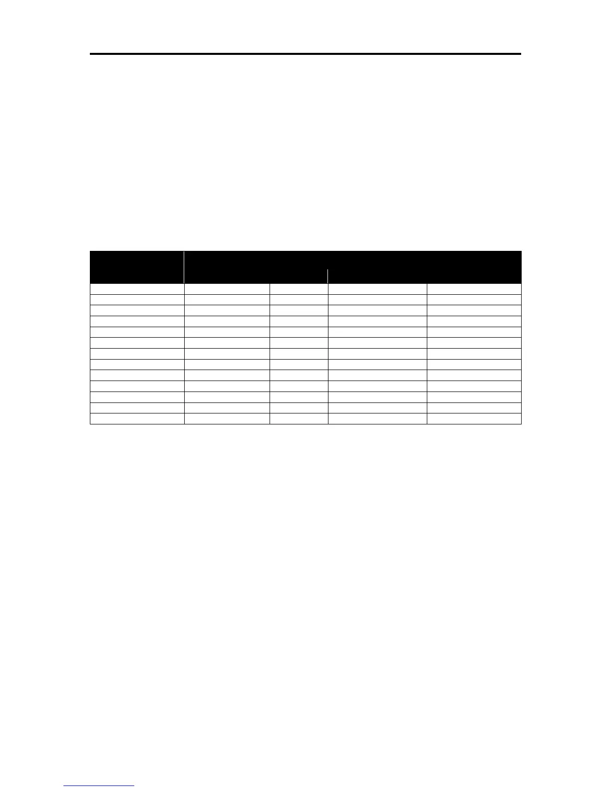
Table 7 Parallel Interface Pin-outs
Signal Levels
Voltage levels 0 V and +5 V (nominal)
Logic levels
Logic one
Driver +2.4 V to +5 V
Receiver +2.0 V to +5 V
Logic zero
Driver 0 V to +0.4 V
Receiver 0 V to +0.8 V
Current requirements
Logic one Source 0.25 ma at +2.4 V
Logic zero Sink 16 ma
Line termination
Data and control 3.3k ohm to +5 V
Strobe 1.2k ohm to +5 V