8 AU-OPR-400Ser-EN,
Rev D
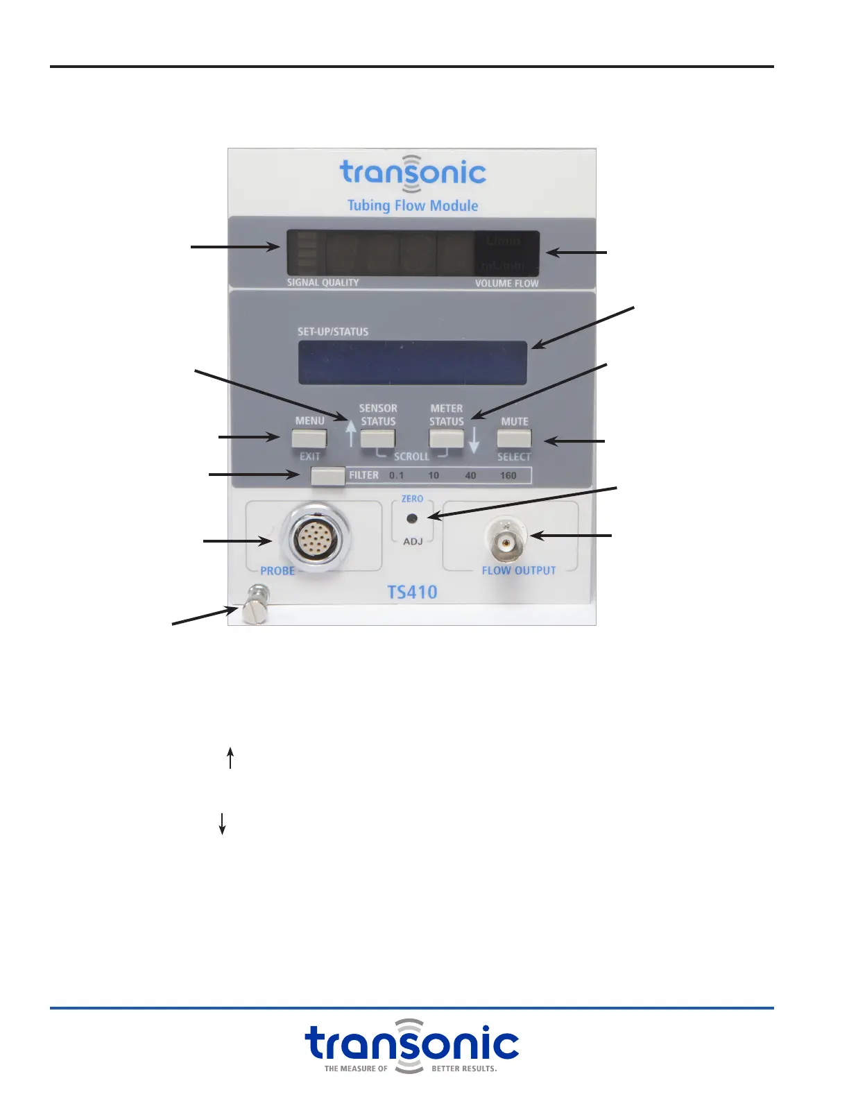
i. TS410 Module: Functions & Controls
A. Front Panel
MENU/ EXIT BUTTON
Enter or exit Menu mode
SENSOR STATUS / SCROLL BUTTON
Displays Sensor calibration and gain
Scrolls up when in Menu mode
METER STATUS / SCROLL BUTTON
Display active Module settings
Scrolls down when in Menu mode
MUTE / SELECT BUTTON
Turns audible alarm on/off
Selects value or enters sub-menu in Menu mode
FILTER SELECTION BUTTON
Sets output lter to 0.1, 10, 40 or 160 Hz
ZERO ADJUST
Adjusts Module to read zero when ow is stopped
PROBE (SENSOR) CONNECTION
Connects Flowsensor or extension cable
BNC FLOW OUTPUT
BNC analog output for mean & pulsatile ow
LED DISPLAY
● Signal quality indicator
● Mean volume ow (mL/min or L/min)
LCD DISPLAY
Module and Sensor settings & Menu mode displays
LED Display
LCD Display
BNC Flow Output
Zero Adjust
Sensor Connection
Menu /
Exit Button
Sensor Status /
Scroll Button
Meter Status /
Scroll Button
Mute /
Select Button
Filter Selection Button
Attachment screw
Fig. 3.5: TS410 Front Panel. Blue labels are active when in Menu
mode. White labels are active in Measure and Status modes.
Signal Quality
Indicator
 Loading...