26 AU-OPR-400Ser-EN,
Rev D
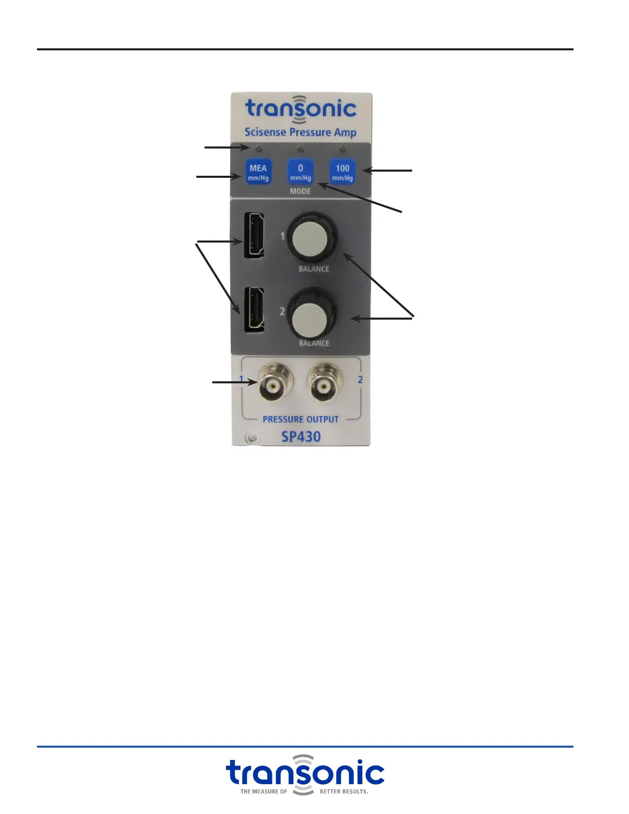
i. SP430 Module: Functions & Controls
MEA (MEASURE) MODE BUTTON
Press to engage pulsatile pressure measurement mode. Light indicates activation.
0 MMHG CALIBRATION BUTTON
Outputs calibration voltage (-2.857 V ±2%) corresponding to 0 mmHg. Light indicates activation.
100 MMHG CALIBRATION BUTTON
Outputs calibration voltage (-0.571 V ±2%) corresponding to 100 mmHg. Light indicates activation.
HDMI CONNECTORS FOR PRESSURE INPUTS
Pressure Catheter extension cable or YS100-ADPT adaptor with extension cable. Two channels available.
Use only Transonic
®
approved HDMI cables.
BALANCE CONTROL KNOBS
Adjusts the pressure output voltage for nullifying zero offset. Each channel is adjusted separately.
NOTE: KNOBS ADJUST EASILY - BEWARE OF UNINTENDED ADJUSTMENTS.
BNC ANALOG OUTPUTS
Pulsatile pressure as a voltage. One output for each channel.
A. Front Panel
MEA (Measure) Mode Button
0 mmHg Calibration Button
100 mmHg Calibration Button
HDMI Connectors
Balance Control Knobs
BNC Analog Outputs
Fig. 5.4: SP430 Transonic Scisense
Pressure Amp Module
Indicator Lights