AU-OPR-400Ser-EN,
Rev D
5
iv. Consoles: Directions For Use
A. Installing Modules
INSTALL ONLY MODULES THAT ARE COMPATIBLE WITH TRANSONIC’S 400-SERIES CONSOLES.
● Be sure the power on the Console is turned off.
● Align wide Flow Modules (TS410 & TS420) with right and left upper and lower rails.
● Align narrow Modules (SP430 Pressure Amplier Modules) on either left or right set of upper and lower
rails.
ALWAYS PLACE SP430 MODULES IN ONE OF THE BAYS (SLOT 3, 4, 5 OR 6)
ON THE RIGHT SIDE OF THE CONSOLE TO ENSURE BEST SIGNAL QUALITY.*
● Slide Module into the Console and push gently on upper and lower portion of the front panel to engage
the rear panel 96-pin connector. The Module will click into place so that the Module is slightly recessed in
the Console.
● Lock into place by tightening the thumbscrew.
● Cover any empty Module slots with a blank panel cover from Transonic
®
. Align the cover holes with the
console top and bottom horizontal rails and screw into place.
B. Removing Modules
Modules may be removed for transfer to another compatible Transonic
®
Console or for repair by a qualied
electrical technician authorized by Transonic
®
.
● Turn power off on the back of the Console.
● Loosen the thumbscrew in the lower left corner of the Module until it is un-threaded and free from the
Console, but not removed from the Module.
● Pull gently on the screw and BNC connector to disengage the rear panel 96-pin connector.
● Slide the Module out of the Console.
● It is recommended to cover any vacant Console bays with a blank panel cover to protect the Console.
C. Synchronization
The timing of ultrasonic signal bursts for Transonic
®
Flow Modules and other ultrasonic devices in the
same frequency range should be synchronized to avoid interference between multiple Probes/Sensors
that are within a 20 cm area. Cross-talk between Probe/Sensor signals causes unpredictable errors in ow
measurement such as increases in zero offset and corrupt ow waveforms. No external synchronization is
required for the SP430 Pressure Module.
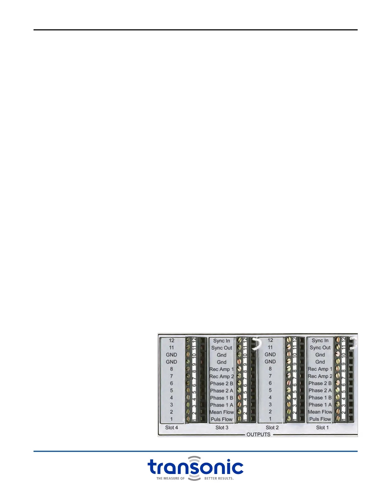
1. SELF-TRIGGERING
Connect Terminal block pin 11
“Synch Out” to pin 12 “Synch
In” via jumper on same terminal
block. This gives the lowest ow
noise and is selected when a
Flow Module runs by itself, or
multiple Flowprobes/Flowsensors
on multiple Modules run
simultaneously with sufcient
distance (>20 cm) between
Probes/Sensors. NOTE: Flow
Modules are shipped from the
factory in self-trigger mode
unless otherwise specied.
Fig. 2.3: Self-triggering Synchronization