AU-OPR-400Ser-EN,
Rev D
19
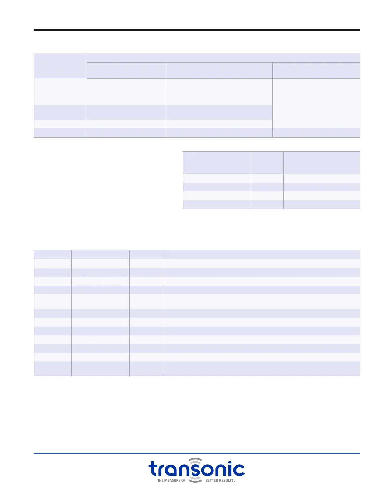
B. Modes of Operation
C. Filter Settings
To record instantaneous ow: set the ow
output [Filter] to a frequency at least 10 times
the ow pulsation or heart rate. The digital
sample rate should be set to a minimum of 3
times the application frequency.
D. Analog Outputs
Transonic
®
Flow Modules output analog signals in the range of -5 volts to +5 volts that are compatible
with most A/D (analog-to-digital) converters of Data Acquisition systems. The back panel analog outputs
generated by the TS420 Module are listed in the table below:
E. Calibration (Cal) Keys
The Calibration Keys store Probe specic calibration information normally located in the Probe’s EPROM.
Probes with small 4-pin connectors do not have a built in EPROM and require the matching Cal Key to
function. NOTE: Cal Keys are Probe specic and should not be used with Probes other than the one for
which they were programmed. Calibration keys will override a Probe connector EPROM if both are present.
NUMBER TERMINAL NAME VOLTAGE DESCRIPTION
12 Sync In N/A In/Out Jumper required for operation; Multi-Module synchronization input
11 Sync Out N/A In/Out Jumper required for operation; Multi-Module synchronization output
10 GND Ground
9 GND Ground
8 Rec Amp 1 0 - 4 V Quality of ultrasound transmission for testing Probe functionality, acoustic coupling or
blockage of ultrasound by air or other impedance mismatch. 2 V = 100%
7 Rec Amp 2 0 - 4 V Same as Rec Amp 1 for a second pair of transducers. 2 V = 100%
6 Phase 2 B ± 5 V Same as Phase 2 A but offset by +4.5 V or -4.5 V
5 Phase 2 A ± 5 V Same as Phase 1 A but for a second pair of transducers
4 Phase 1 B ± 5 V Same as Phase 1 A but offset by +4.5 V or -4.5 V
3 Phase 1 A ± 5 V Acoustic velocity of uid used in ultrasound indicator dilution studies
2 Mean Flow ± 5 V Average volume ow output, ltered at 0.1 Hz
1 Puls Flow ± 5 V Instantaneous pulsatile volume ow output, ltered at 10, 40, or 160 Hz depending on
the Module front panel [Filter] setting. Default to 160 Hz if 0.1 Hz lter is used.
Only PAU-Series Probes have two transducer pairs, all other Probe series have a single pair. For single pair Probes Phase 2 and Rec Amp
2 outputs are identical to Phase 1 and Rec Amp 1 outputs.
MODE
OUTPUTS
FRONT DIGITAL DISPLAY FRONT ANALOG DISPLAY
MEAN & PULSATILE FLOW
Front BNC/ Rear Analog
MEASURE
Bar indicator of signal quality
Average ow in mL/min or L/min
Start-up & error messages
Instantaneous volume ow= ow reading x
scale factor
Flow = recorded voltage x scale factor
Bidirectional ow output ± 5 V
TEST
Probe size and received signal
quality
Proportional value of received signal amplitude
1 V = standard normalized level
ZERO 0 mL/min 0 V = zero ow (calibration reference) 0 V = 0 mL/min
SCALE Scale factor ow value 1 V = scale factor ow (calibration reference) 1 V = scale factor ow
TS420 Module: Functions & Controls
HEART RATE OR
APPLICATION FREQUENCY
LOW PASS
FILTER
SETTING
RECOMMENDED MINIMUM
DIGITAL SAMPLE RATE FOR
DATA ACQUISITION
Average Flow Recording 0.1 Hz 0.3 Hz
Pulsatile to 60 beats/minute 10 Hz 30 Hz
Pulsatile to 240 beats/minute 40 Hz 120 Hz
Pulsatile to 960 beats/minute 160 Hz 500 Hz