AU-OPR-400Ser-EN,
Rev D
27
B. Modes of Operation
C. Analog Outputs
Transonic
®
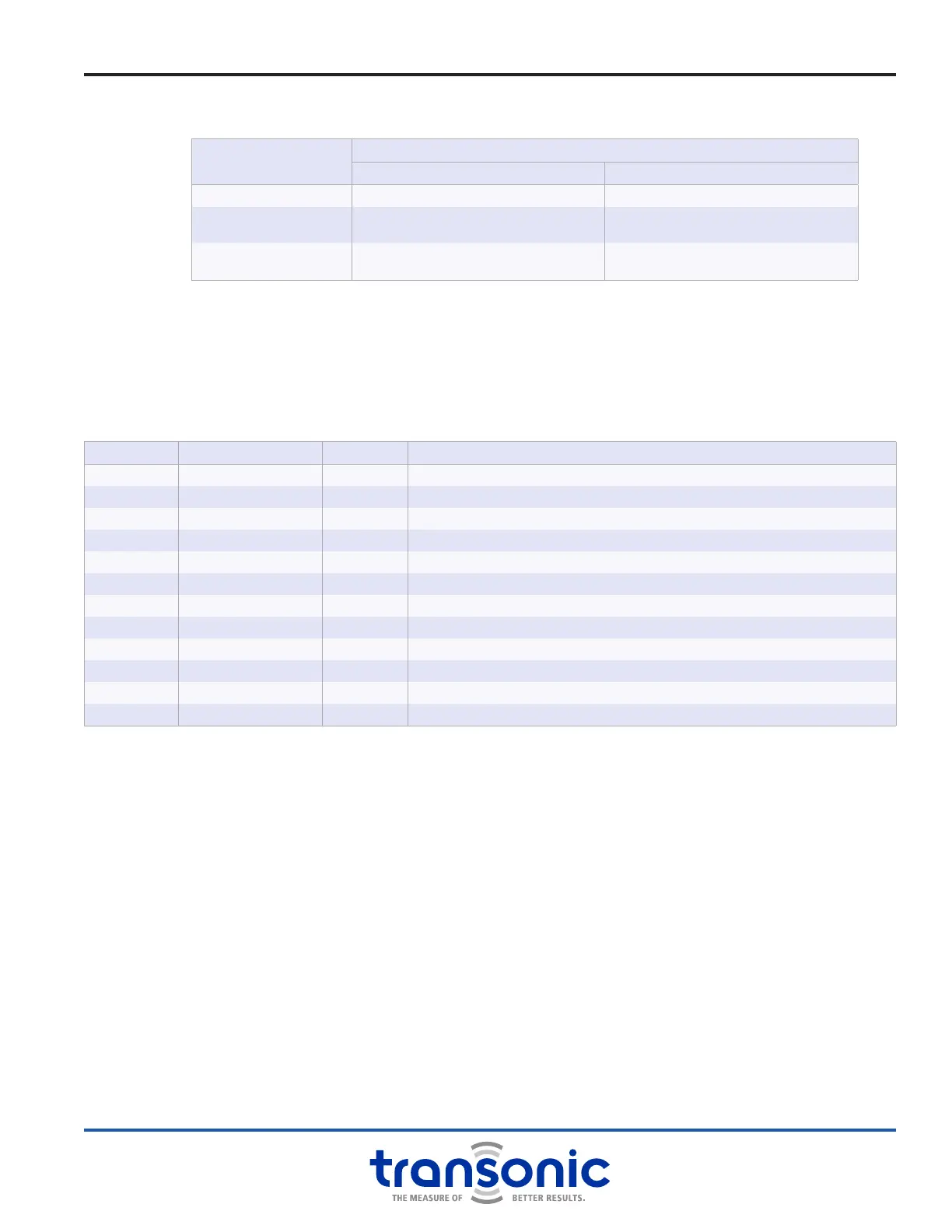
Pressure Amp Modules output analog signals in the range of -5 volts to +5 volts that are
compatible with most A/D (analog-to-digital) converters of data acquisition systems. The back panel analog
outputs generated by the SP430 Module are listed in the table below:
NUMBER TERMINAL NAME VOLTAGE DESCRIPTION
12 Inactive Inactive
11 Inactive Inactive
10 GND Ground
9 GND Ground
8 Inactive Inactive
7 Inactive Inactive
6 Inactive Inactive
5 Barometric Pressure ± 5 V Barometric Air Pressure
4 Inactive Inactive
3 Pulse Pressure 2 ± 5 V Pulsatile pressure from Sensor 2
2 Inactive Inactive
1 Pulse Pressure 1 ± 5 V Pulsatile pressure from Sensor 1
MODE
OUTPUTS
FRONT ANALOG BNC REAR ANALOG TERMINAL BLOCK
MEA MMHG (MEASURE) Pulsatile pressure in volts Pulsatile pressure in volts
0 MMHG
-2.857 V ±2% (corresponds to 0 mmHg)
Acceptable range: -2.800 V to -2.914 V
-2.857 V ±2% (corresponds to 0 mmHg)
Acceptable range: -2.800 V to -2.914 V
100 MMHG
-0.571 V ±2% (corresponds to 100 mmHg)
Acceptable range: -0.560 V to -0.582 V
-0.571 V ±2% (corresponds to 100 mmHg)
Acceptable range: -0.560 V to -0.582 V
SP430 Module: Functions & Controls
 Loading...