AU-OPR-400Ser-EN,
Rev D
1
I. Introduction
NOTE: In this manual, “Consoles” refer to T402 & T403 Multi-channel Consoles.
NOTE: “Modules” refer to the TS420 Perivascular Flow Modules, TS410 Tubing Flow Modules & SP430
Transonic Scisense Pressure Amplier Modules.
NOTE: In this manual, “Probe” and “Flowprobe” refer to Transonic
®
Precision Perivascular Flowprobes.
NOTE: “Sensor” and “Flowsensor” refer to Transonic
®
Clamp-on and Inline Tubing Flowsensors.
NOTE: “Transducers” refer to Pressure Transducers including Transonic Scisense Pressure Catheters and/or
Transpac
®
IV Pressure Transducers. “Catheters” refer to Transonic Scisense Pressure Catheters.
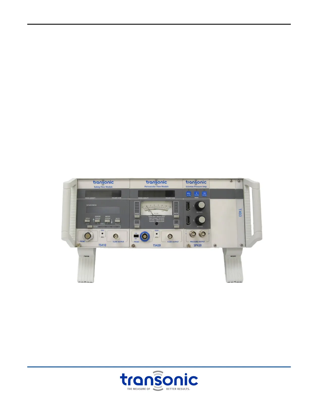
Mix and match the measurement capabilities you need in a single instrumentation Console. T402 and T403
line cord powered Consoles are multi-channel capacity cases with a shared universal power supply and
back-panel analog outputs compatible with most data acquisition systems. The T402 and T403 Consoles
accept any 400-Series Modules:
● TS420 Perivascular Flow Module: for in vivo arterial/ venous blood ow
● TS410 Tubing Flow Module: for volume ow of uid in tubing
● SP430 Transonic Scisense Pressure Amplier Module: for arterial/venous blood pressure
BOTH A CONSOLE AND A MODULE ARE REQUIRED TO TAKE MEASUREMENTS.
Fig. 1.1: T403 Console with TS410 Tubing Flow Module, TS420 Perivascular Flow Module
and SP430 Transonic Scisense Pressure Amp