AU-OPR-400Ser-EN,
Rev D
21
iii. TS420 Module: Functional Tests
These functional tests are suggested to acquaint a new user with Transonic
®
400-Series Flow Modules and
Transonic
®
Perivascular Flowprobes and to check for damage incurred during shipment. If the apparatus
does not function as described during this initial operation, please call Transonic
®
customer service or your
authorized Transonic
®
provider or sales representative.
A. Flow Module Set-up
1) Verify that the Console’s rear panel synchronization terminals are properly connected. (See Console
synchronization instructions, page 5)
2) Connect Console power cord to grounded power receptacle.
NOTE: Do not operate unless Console is electrically grounded via supplied power cable.
3) Turn on power switch on back panel of Console.
a) The TS420 starts up in Test Mode to encourage testing of the Flowprobe prior to use.
b) Digital Display will scroll “TSI ✓” and display “NO.PR.” NOTE: Module settings cannot be adjusted
without a Flowprobe connected.
4) Connect a Flowprobe (or extension cable with a Flowprobe) to the front panel mounted self aligning
10-pin connector. If a 4-pin chronic connector is used, also insert the calibration key into the [Cal Key]
socket on the front panel next to the Probe connector.
a) Digital Display will scroll “No Sig” and Probe size.
B. Perivascular Flowprobe Signal Quality Test
1) Attach the Flowprobe to the Module and set the [Mode] to “Test.”
2) Immerse the Probe in a soft plastic beaker lled with degassed water or saline.
NOTE: Hard containers reect the ultrasound signals and will cause the Probe to appear to have high or
drifting zero offset values. Sponge may be inserted in the container to absorb extraneous signal.
3) Dislodge any air bubbles from the surfaces of the Probe. Shaking the Probe under water may be
sufcient. A ne gauge paint brush is useful especially with smaller Probes which can hold air bubbles.
4) Observe Flow Module’s front panel indicators. The “No Sig” message will be replaced with “Good Sig” as
good acoustic conduction is established with the Probe. A dry Probe may need to be immersed in water
or saline for several minutes before this occurs. Swishing the Probe back and forth helps to speed up the
process. The Probe’s received signal stabilizes when the surfaces are sufciently wetted and conrms
acoustic transmission of the ultrasound signal.
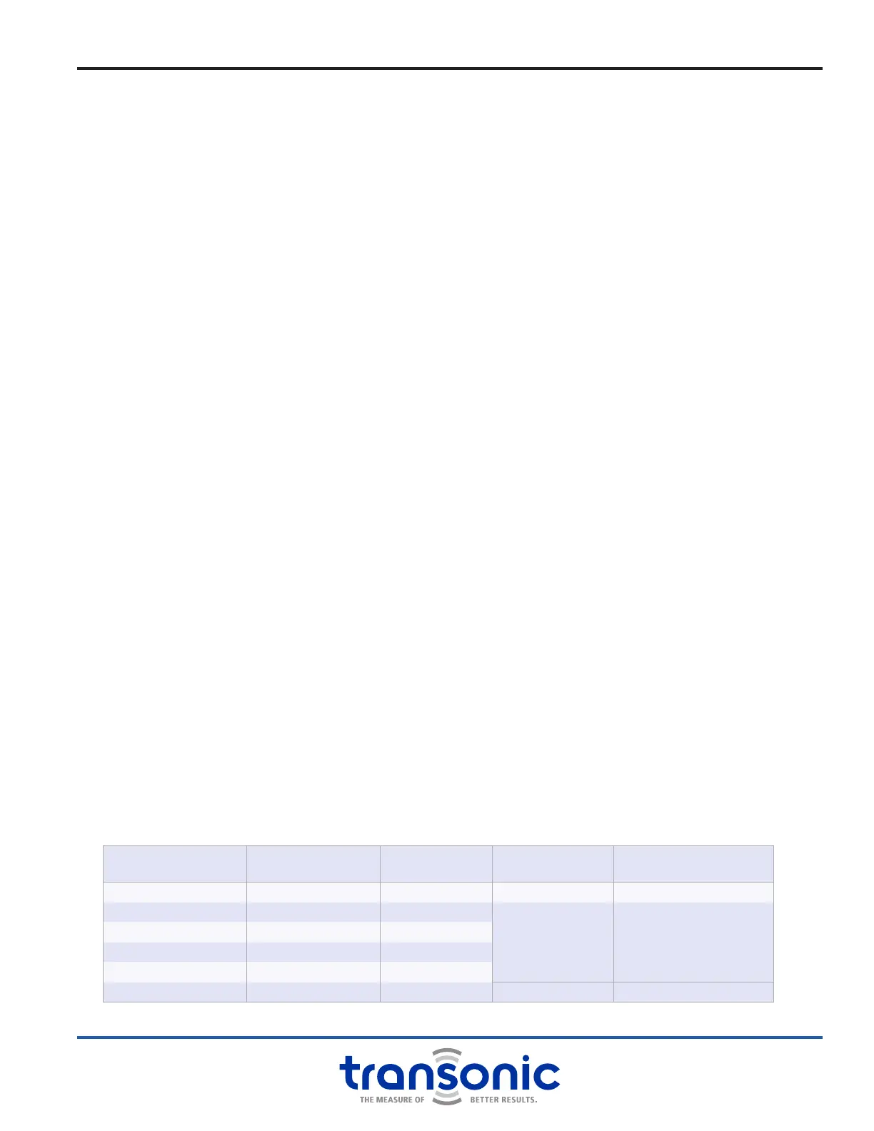
5) The Signal Quality Indicator should be fully illuminated - all 5 bars will be lighted. NOTE: If the Flowprobe
has less than 3 bars lit during the water/ saline test (without interruption from bubbles) do not use the
Flowprobe for measurements. Contact your Transonic
®
representative for additional troubleshooting or
repair return instructions.
SIGNAL STRENGTH SIGNAL QUALITY BAR DISPLAY ANALOG DISPLAY
“REC AMP” VOLTAGE
FROM REAR PANEL
over 80% Good 5 bars lit over 0.8 V over 0.8 V
60% to 80% Good 4 bars lit
proportional reading proportional reading
30% to 60% Good 3 bars lit
20% to 30% Low 2 bars lit
10% to 20% Low 1 bars lit
under 10% No Signal no bars lit under 0.1 V under 0.1 V
 Loading...