AU-OPR-400Ser-EN,
Rev D
23
iv. TS420 Module: Directions For Use
FLOWPROBE PREPARATION
At least 10 minutes before acute use, submerge the Flowprobe in sterile saline. This “soaking” of the Probe
eliminates random drift in zero offset which a dry Probe may exhibit when applied to a vessel. If only
chronic measurements are needed, the 10 minute Probe soak may be omitted. The Flowprobe has been
factory calibrated to meet Transonic
®
Flowprobe specications when applied to a living vessel (see RL-20-ds).
If a more precise zero baseline than that specied is needed, the Probe’s zero must be obtained in situ by
vessel occlusion. A zero reading in a beaker of liquid generally will differ from an “in situ” zero.
VESSEL SITE SELECTION
The Flowprobe is largely insensitive to turbulence and/or vessel-Probe alignment and may be applied
effectively on straight segments or near side branches of the vessel. When applied on a curved segment of
the vessel, the plane dened by the Probe’s transducers and reector bracket should be perpendicular to
the plane dened by the curve of the vessel.
VESSEL PREPARATION
Use blunt dissection to free just that section of the vessel to which the
Probe will be applied; you need not “clean” it for ultrasonic permeability,
but carefully remove all fatty tissue in the Probe’s acoustic pathway. Try
not to deect the vessel from its natural course. If absolute ow into or
out of an organ is a study parameter, all unligated side branches between
the measurement site and the organ must be occluded during ow
measurements.
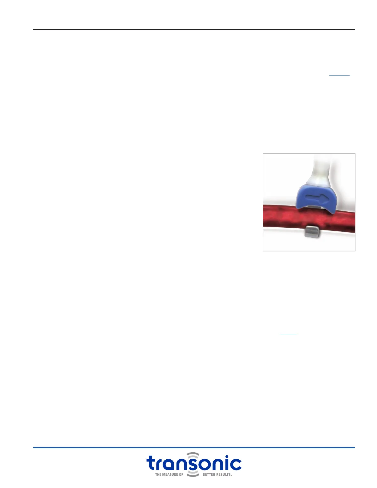
PROBE APPLICATION
The Flowprobe is applied so that the vessel under observation lies within
the sensing window formed by the Probe’s transducer body and the
attached reector bracket (Fig. 4.9). The optimal alignment is to have the
vessel run perpendicularly through the Probe’s window. The Flowprobe
may be oriented in either direction relative to upstream/downstream ow;
preferred orientation allows an easy exit for the cable.
ACUTE APPLICATION
Excessive vessel manipulation may cause vessel spasm and should be avoided. Often, securing the
Flowprobe in place with a temporary suture is helpful for preventing vessel occlusion or twisting. For
proper function, the space between the circular vessel and the rectangular reector bracket must be lled
with a suitable ultrasonic couplant.
STANDARD COUPLANTS
For acute applications, proper ultrasonic contact between Probe and vessel must be provided using an
acoustically matched couplant (see Acoustical Couplants for Acute Measurements RL-9-tn). Surgilube &
H-R Lubricating Jelly are recommended couplants. Banked blood (if the site’s geometry is suitable) may
be applied to provide this acoustic coupling between vessel and Flowprobe but should not be used for
small vessels. At a highly pulsatile site, movement of a liquid couplant within the sensing window will be
measured as ow and will affect net measurement. For accurate measurements, the vessel should ll 75%
- 99% of the Flowprobe lumen. This will eliminate Probe positional sensitivity. It is also easier to maintain
coupling with a close tting Probe as less gel is required and surface tension will hold gel in place.
ACOUSTIC COUPLING
Proper coupling is veried by observing the Module’s diagnostic messages in “TEST” mode. On the digital
dispaly, the “(Probe size)-Gd” must be displayed. The analog display must indicate a Probe relative received
signal strength which exceeds 60% of the Probe’s reading in saline (e.g., a new Probe will show around 1.0
in saline; its acute reading must exceed 0.6.) A low signal strength reading indicates that air bubbles and/
or fat particles are in the acoustic window. They must be removed before the Probe can attain its stated
measurement accuracy.
Fig. 4.9: Flowprobe placement
 Loading...