Installing the System MicronNav System
0656-SOM-00001-07 16 © Tritech International Ltd.
3.1.5. Electrical Connection to the Surface USBL Dunking Transducer
The USBL Dunking Transducer is supplied complete with underwater cable moulded directly
onto the head and a DB-25 connector at the dry side for connection directly into the USBL
connector on the rear of the MicronNav100 Interface Hub.
3.1.6. Electrical Connection to the Surface MicronNav100 Interface Hub
The surface MicronNav100 Interface Hub requires power from a 90 to 264V AC supply 47
to 63Hz, or a 12 to 36V DC supply - power consumption from either source will be typically
4.8W (with no additional external device load).
Communications from the MicronNav100 Interface Hub to the Subsea head (if being used
with Micron/SeaSprite Sonar) is via a DE-9 socket which connects to Port B plug on the rear
of the unit.
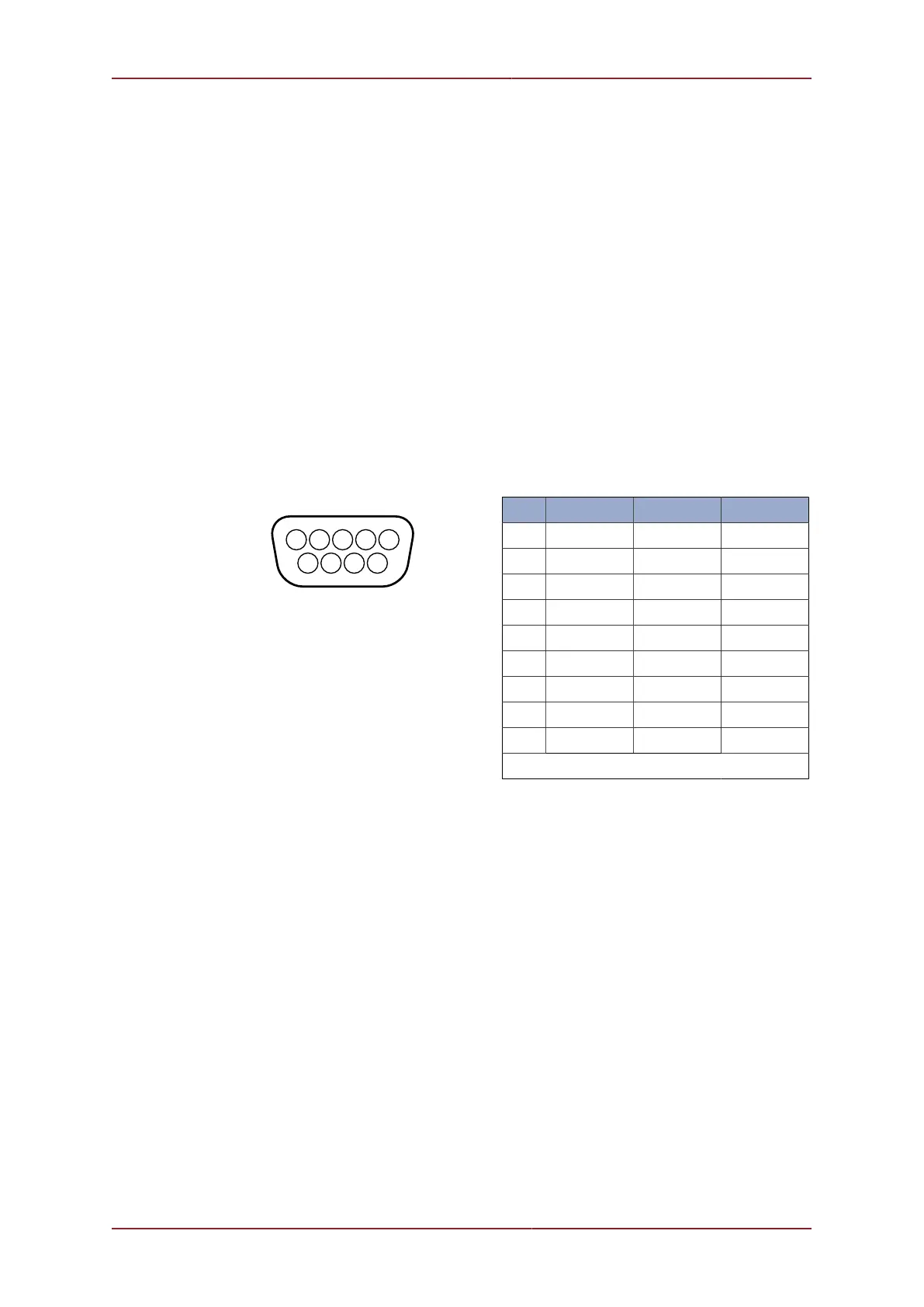
Connections to the DE-9 socket on Port B are as follows:-
Pin RS232 RS422 RS485
1 ‡ ‡ ‡
2 RX TX.A TX/RX.A
3 TX TX.B TX/RX.B
4 ‡ ‡ ‡
5 GROUND GROUND GROUND
6 ‡ ‡ ‡
7 ‡ RX.B ‡
8 ‡ RX.A ‡
9 ‡ ‡ ‡
‡ = connected for handshaking only.
Communications from the MicronNav100 Interface Hub to the computer running the
MicronNav Seanet application software is via a USB Type-A to Type-B cable supplied with
the system, connection is to the rear of the unit.
3.1.7. External Computer Data Link Electrical Connections
If the MicronNav data is required by a third party software package running on an external PC
then connection from the Surface MicronNav100 Interface Hub to the external PC is made
via one of the four serial interface connectors located at the rear of the unit, Port A, B, C or
D. (Note: If the system is being used in Responder mode Port B will be used for the Sonar
communications and will not available for this).
If ports A, B or C are to be used for external communications a DE-9 socket should be wired
as above, if port D socket is to be used a DIN-45322 (6 pin) plug is required and should be
wired as follows: