Setting-Up
it off and then on again. If necessary, refer to the Portable Printer Operation
and Service Manual.
Connecting/Wiring the Analog/Alarm Output Connector
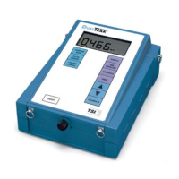
The Model 8520 D
USTTRAK Aerosol Monitor is capable of providing an
analog output voltage signal that is proportional to the displayed
concentration. It also contains a switch closure that is tied to an alarm value
(see Chapter 3, “Operation
,” for complete specifications and operational
information for these features). The D
USTTRAK monitor is supplied with an
output cable. The cable contains a 4-pin, mini-DIN connector. See
Figure 2-2 below.
Figure 2–2: Analog/Alarm Connector Pin-Outs
Since every application of this function will have unique requirements, the
customer is responsible for making connections to their own equipment. The
output cable contains a label, showing the wiring diagram/pin-outs.
Please see TSI Application Notes ITI-073 and ITI-074 for complete
information and examples of wiring and using the Analog/Alarm Outputs.
These Application Notes are available at the TSI website,
http://www.tsi.com
.
1
2 3
4
 Loading...