9-6
3.2.REASSEMBLY steps
1) Install the draft control linkage.
2) Install the position control linkage.
3) Install the pilot spool control linkage.
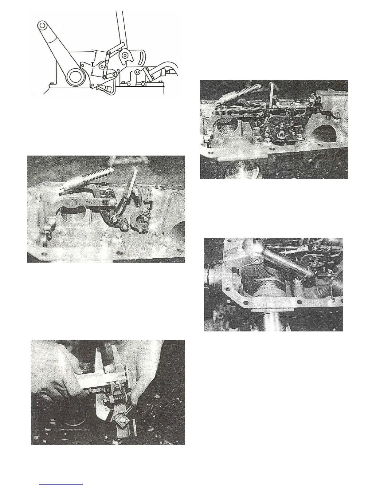
Fig.9-5
Fig.9-6
Fig.9-7
Note:
Before installing the linkage,set the load of the
pressure spring to be 9.5-9.8Kgf(20.9-21.6 lbs)by
making the installed length of the spring 21.5 mm
(0.0847 in) (Fig.9-7)
4) Install the main control valve and return spring
5) Install the lift crank temporarily along with
the feed back link.Install the piston rod on the
lift crank.
Fig.9-8
Note:
Drive the roll pin into the piston pin through
the lift crank and lock the pin with wire.
6) Install the lift shaft and lift crank together in
accordance with the aligning marks on them.
Fig.9-9
 Loading...