2.3. OPERATIONS
The operations of this valve will be explained by reference to the operation diagrams in Fig.9-31 and 33.
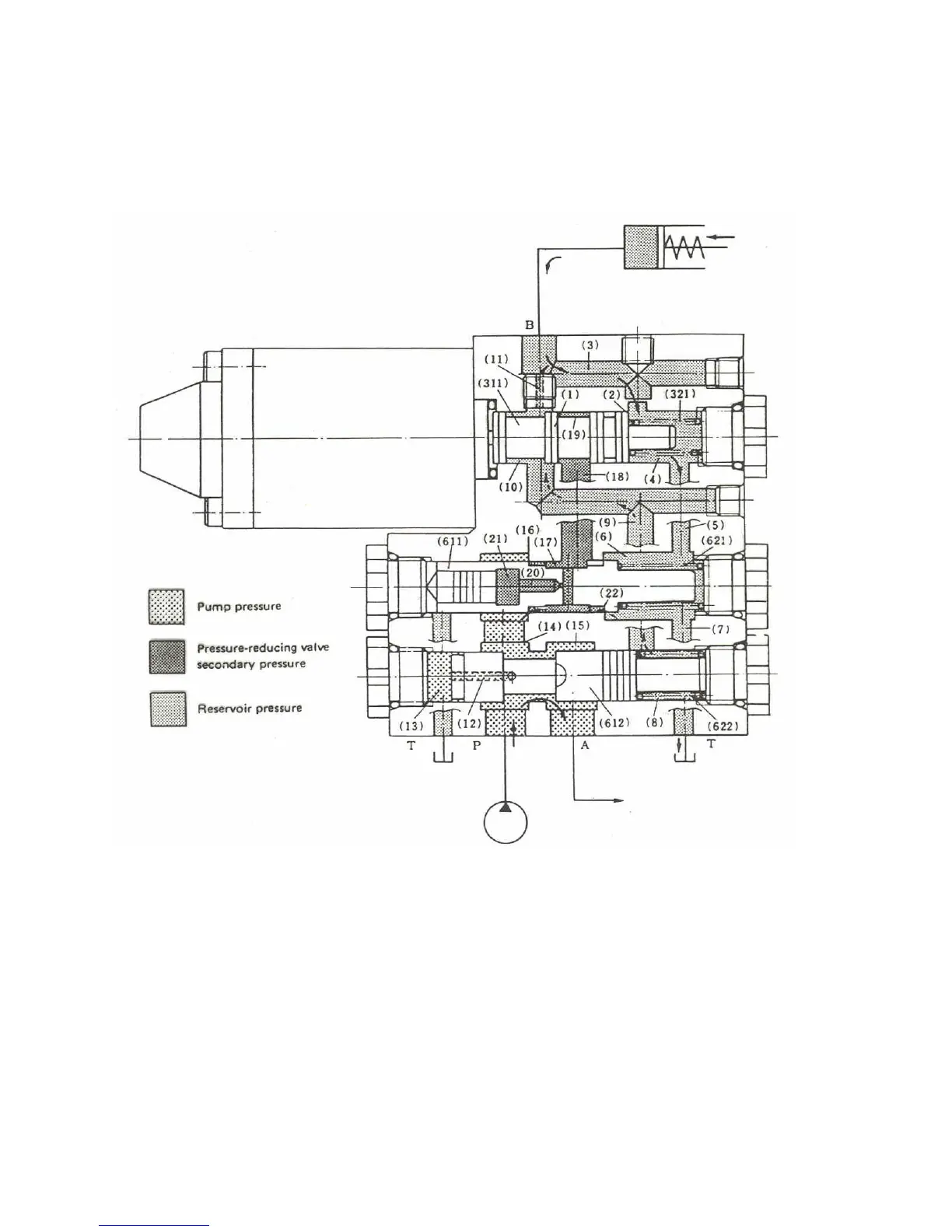
Port P is connected to the pump;port A is connected to the main circuit(port P of the control valve) ; port
B is connected to the clutch cylinder;port T is connected to the tank.
1) OFF position
9-24
While the solenoid is switched off, the fluid in the cylinder is unloaded to the tank and all fluid from
the pump flows to the main circuit with no branching. The details of this operation are described
below: Changeover spool (311) is pushed leftward by spring(321), so that orifice(1) is closed
whereas orifice(2) is opened. Consequently, the fluid in the cylinder flows to the tank from port B,
via passage(3), chamber(4), passage(5), chamber(6), and passage(7). As the fluid in sequential valve
spring chamber(8) is connected to the tank via passage(9), chamber(10), orifice(11), and passage(3),
the pressure in chamber(18) becomes 0 kgf/cm
2
(0 psi) and the force for pushing sequential valve
spool(612)leftwards is just the force of spring(622). The pump delivered fluid is led to chamber(14)
through passage(12) and pushes the sequential valve spool rightwards and flows to the main circuit
from port A via chamber(14 and 15). At this point, if the pressure at port A, that is, the pressure at
port P is low because of the unloading of the main circuit, pressure-reducing valve spool(611) is
pushed leftwards by the force of spring(621) and orifice(16) is fully opened,
Fig.9-31
 Loading...