2)ON position
When the solenoid is switched on, a specified amount of the fluid from the pump is branched off to the
clutch cylinder. When the clutch is engaged and the cylinder pressure rises, the cylinder pressure is
maintained at a specified level by reducing the amount of the fluid branched off. The detail of this
operation will be explained in two situations: when the main circuit pressure is higher than the port B
regulated pressure(pressure-reducing valve secondary pressure) and when the main circuit pressure is
lower than the regulated pressure.
ㆍWhen the main circuit pressure is higher than the regulated pressure:
When the main circuit pressure is higher than the regulated pressure, the sequential valve(612+622)
does not work when sequential valve spool(612) is pushed rightwards.
When the solenoid is switched on, the changeover spool is pushed rightwards and orifice(1) is opened
to connect passage(18) to chamber(10) whereas orifice(2) is closed to block the passage to the tank.
Some of the fluid delivered from the pump is led to the clutch cylinder from port B via chamber(23),
orifice(16), chamber(17), passage(18), chamber(10), and orifice(11). At this point, provided that the
orifice(16), chamber(17), passage(18), chamber(10), and orifice(11). At this point, provided that the
cylinder actuating pressure is 1 kgf/cm
2
(14 psi): the pressure at port B, the down side pressure of
orifice (11) becomes 1 kg/cm
2
(14 psi), whereas the up side pressure: the pressure in chamber(10) is
the same as those in chambers(18 and 17): 15 kgf/cm
2
(213 psi), which is maintained by the pressure-
reducing valve in the same way as it does in the OFF position. Consequently, the pressure differential
across orifice(11) is rendered constant and the fluid flow through orifice(11) remains constant. With
this, the engaging time for the clutch is specified.
At the end of the clutch stroke, the pressure at port B rises, but when it reaches 15 kgf/cm
2
(213 psi),
the pressure differential across orifice(11) becomes zero and naturally the fluid flow through
orifice(11) stops. As this pressure is maintained by the pressure-reducing valve, the clutch pressure is
also kept constant.
9-25
which renders the pressure in chambers(17, 18, and 19) the same as the pressure at port P. When the
main circuit pressure is higher than the pressure regulated by spring(621): 15kgf/cm
2
(214 psi),
pressure-reducing valve spool(611) works to maintain the pressure in chamber(17), the pressure-
reducing valve secondary pressure, at a specified level.
The operation of the pressure-reducing valve with a regulated
pressure of 15kgf/cm
2
(213 psi) will now be explained.
The pressure in chamber(17) is led to chamber(21) through
passage(20) and pushes the pressure-reducing valve spool
rightwards. When the pressure in chamber(17) is higher than
15kgf/cm
2
(213 psi), pressure-reducing valve spool(611) is
pushed rightwards, which closes orifice(16) to block the
passage from the higher pressure side and at the same time
opens orifice(16)leading to the tank, and as a result the
pressure in chamber(17) lowers.
Conversely, when the pressure in chamber(17) is lower than the specified pressure, spool(611) is
pushed leftwards by the force of spring(621), which results in the closing of orifice(22) and the
opening of orifice(16). This leads to a rise in the pressure-reducing valve secondary pressure is
maintained at 15kgf/cm
2
(213 psi).
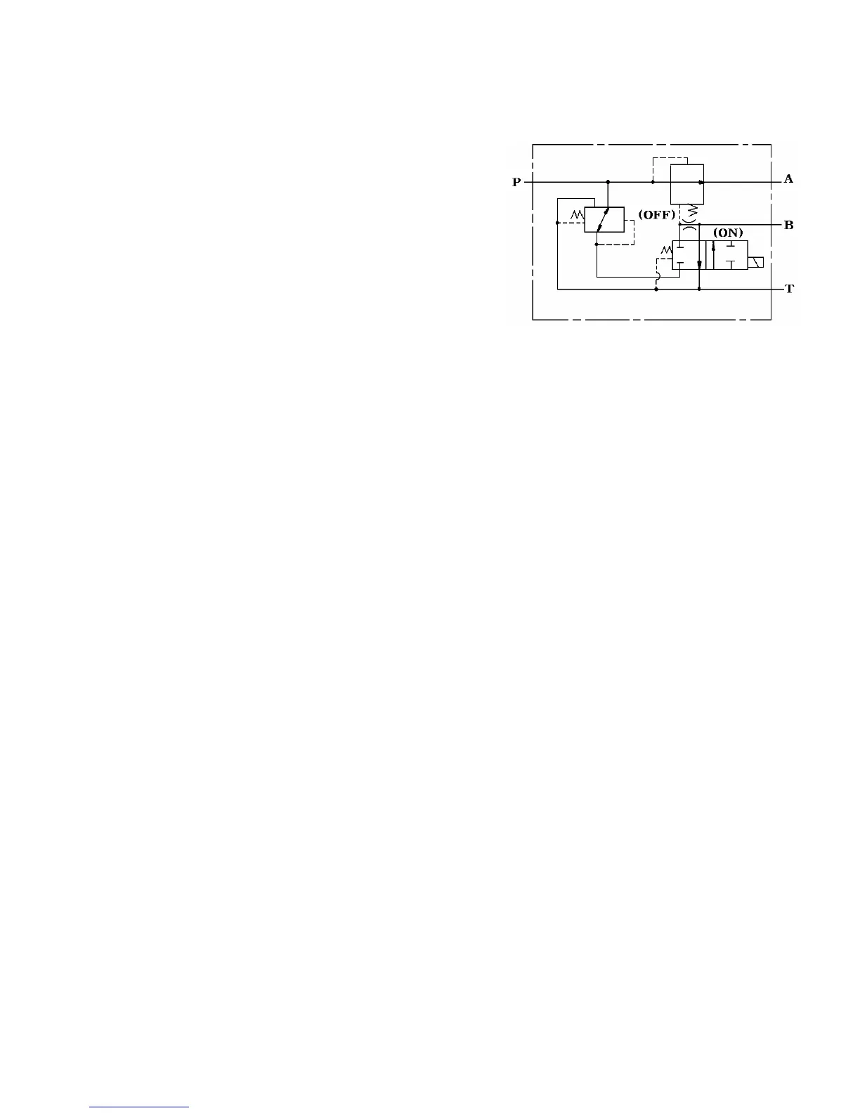
Fig.9-32
Circuit diagram in the Off position
 Loading...