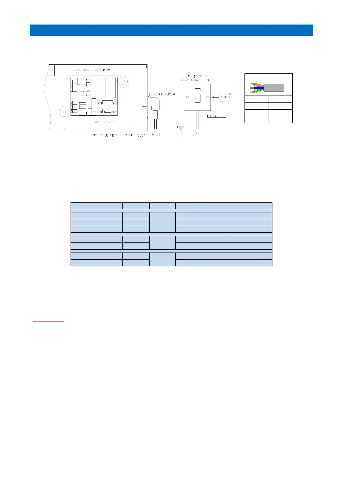
MAINS SUPPLY
The 240V AC mains supply should be taken from a local fused spur.
Connect the PA Amplifier to the fused spur using 0.5mm 3-core flex (Type 2183Y) and the IEC socket provided. Secure
the flex to the chassis using a cable tie to prevent the mains lead being inadvertently unplugged. The spur should be
fitted with a 5A fuse.
TERMINATION
3 cables are provided for connection to the Advent XT2 controller’s termination board - see table below for
connections and colour codes. Also see Drg. No. ZXT900 sheet 2.
Note: Transformer 1/2 connections are not polarity conscious.
2
nd
PA AMPLIFIER TERMINATION
On installations with more than 80 intercoms a second ZXT901 PA Amplifier is required. The EN/AUD/0V and data
RS485+/RS485- are simply connected in parallel with the first PA Amplifier, however the Transformer output of the
second PA Amplifier must be connected to the Termination Board PA AMP 2 INA/PA AMP 2 INB terminals.
IMPORTANT: when 2 PA Amplifiers are fitted the site wiring AUDIO 2 SP1/SP2 must be split into 2 legs. Ideally the
number of intercoms on each leg should be shared 50/50, i.e. if there’s 120 intercoms in total connect 60 on each leg
rather than 80 on one leg and 40 on the other. The 2
nd
leg must have the AUDIO 2 SP1/SP2 pair connected to the
Termination Board SP3/SP4 terminals instead. See Tynetec Drg. No. WD0298.
SMPSU & DC-DC MODULES
The 15V/105W switch mode power supply unit (P/No. W00586) is factory set to 13.75V DC output to supply the two
24V DC-DC converters and the PA amplifier board. This voltage also charges the 12V standby battery. The SMPSU has
solid state overload protection and contains no user serviceable parts.
The two 24V/50W DC-DC converter modules (P/No. W00590) are factory wired to provide +/- 24V DC supply for the
PA amplifier board. The DC-DC converters have solid state overload protection and contain no user serviceable parts.
PROGRAMMING
The All Call and Fire Tone options must be enabled in the Onsite & General Setup programming - see the Advent XT2
Programming Manual (Doc No FM0815).