Doc No. FM0804 issue 4 Page 24
An end of line 4K7 resistor is NOT required with the
normally closed configuration.
Options DIL switch 7
in the intercom must
be ON for normally
closed pullcords
Options DIL switch 7
in the intercom must
be OFF for normally
open pullcords
An end of line 4K7 resistor must be fitted across the
COM & N/O terminals on the LAST pullcord in normally
open configuration.
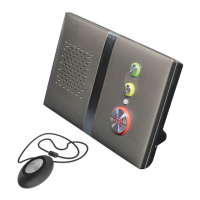
16. INTERCOM UNIT AUXILIARY DEVICES
The intercom has the facility to connect ceiling mounted pullcords, smoke detectors, PIR detectors, 4 additional inputs
and a hard of hearing strobe light within each dwelling.
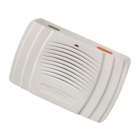
CEILING PULLCORDS
NORMALLY OPEN CONFIGURATION
NORMALLY CLOSED CONFIGURATION
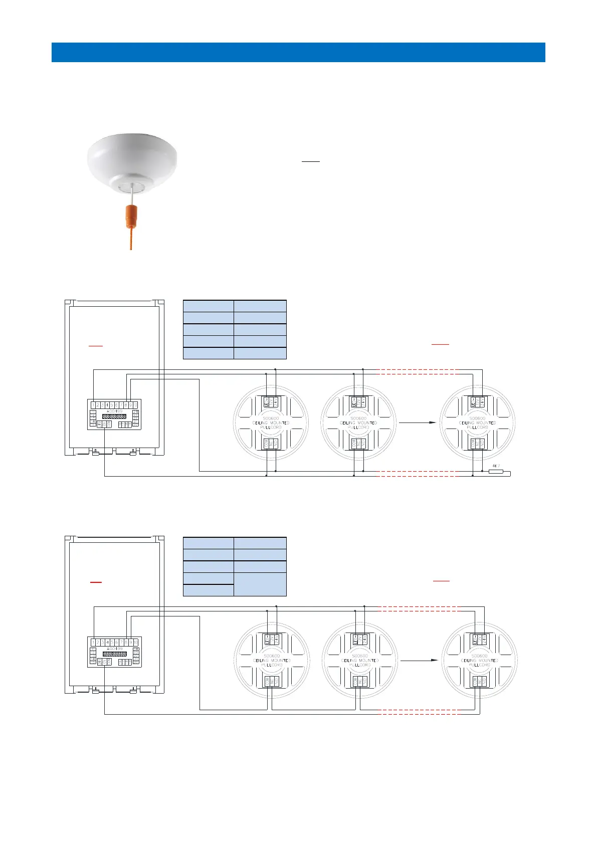
Tynetec Ceiling Pullcord Part No. S00600.
Up to 5 pullcords with 24V LED’s can be connected per intercom.
No limit if LED’s are NOT connected.
Pullcords can be wired in a normally open or normally closed configuration.
Normally open pullcords will require a 4K7 end of line resistor fitted in the
last pullcord. For normally closed DIL switch 7 in the intercom must be ON
and NO end of line resistor is required.
Note: if existing pullcords are being re-used check the LED can operate from
a 24V DC supply.