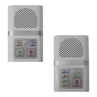
The optional XT2 Manager’s Display Panel (P/No. ZXT905) is a wall
mounted 10.1” Windows 10 touch-screen PC.
This is will display alarm calls and log all system activity with the time
and date. It can also be used for setting up system features, software
updates and to allocate Telecare devices.
The Manager’s Display Panel can have a large “Notice Board” monitor
connected to display information for residents in communal areas.
Up to 32 Manager’s Display Panels can be connected per system.
Each panel requires a local mains supply and an Ethernet connection to
the XT2 controller. An Ethernet Switch will be required on installations
with more than one panel.
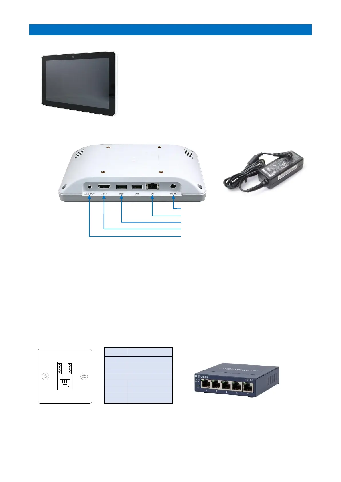
PANEL CONNECTIONS
POWER SUPPLY
The Manager’s Display Panel should be located within close proximity of a mains supply where the PSU module can be
plugged-in and connected to the DC-IN port. The PSU module has a 0.8 metre long mains lead plus a 1.8 metre low
voltage lead – this must not be cut down or extended.
Note: the Manager’s Display Panel has no battery standby and is therefore not operational during a mains failure.
ETHERNET
If there’s only one Manager’s Display Panel and it’s within 3 metres cable run of the Advent XT2 controller then
connect the LAN port to the XT2 Ethernet 1 (CON3) using the 3m CROSSOVER Patch Lead provided.
If there’s only one Manager’s Display Panel but it’s a distance away, then an RJ45 wall socket should be fitted locally
to the XT2 controller and Manager’s Panel and wired between using Cat5e Ethernet U/UTP cable (Belden Type:
1583E.00B100) or equivalent. Wire all 8 connections between the wall sockets, the max cable length must not exceed
100 metres. Use the 3m Crossover Patch Lead at the XT2 end and the standard 2m Patch Lead at the Panel end.
If there’s multiple Manager’s Display Panels, then an Ethernet Switch will be required. Connect the XT2 Ethernet 1
port and each Panel to the Ethernet Switch using local RJ45 wall sockets and standard 2m Patch Leads. Wire between
the RJ45 wall sockets as described above. A 5 Port Ethernet Switch (Tynetec P/No. W07485) can be used for up to 4
panels, larger switches are available.