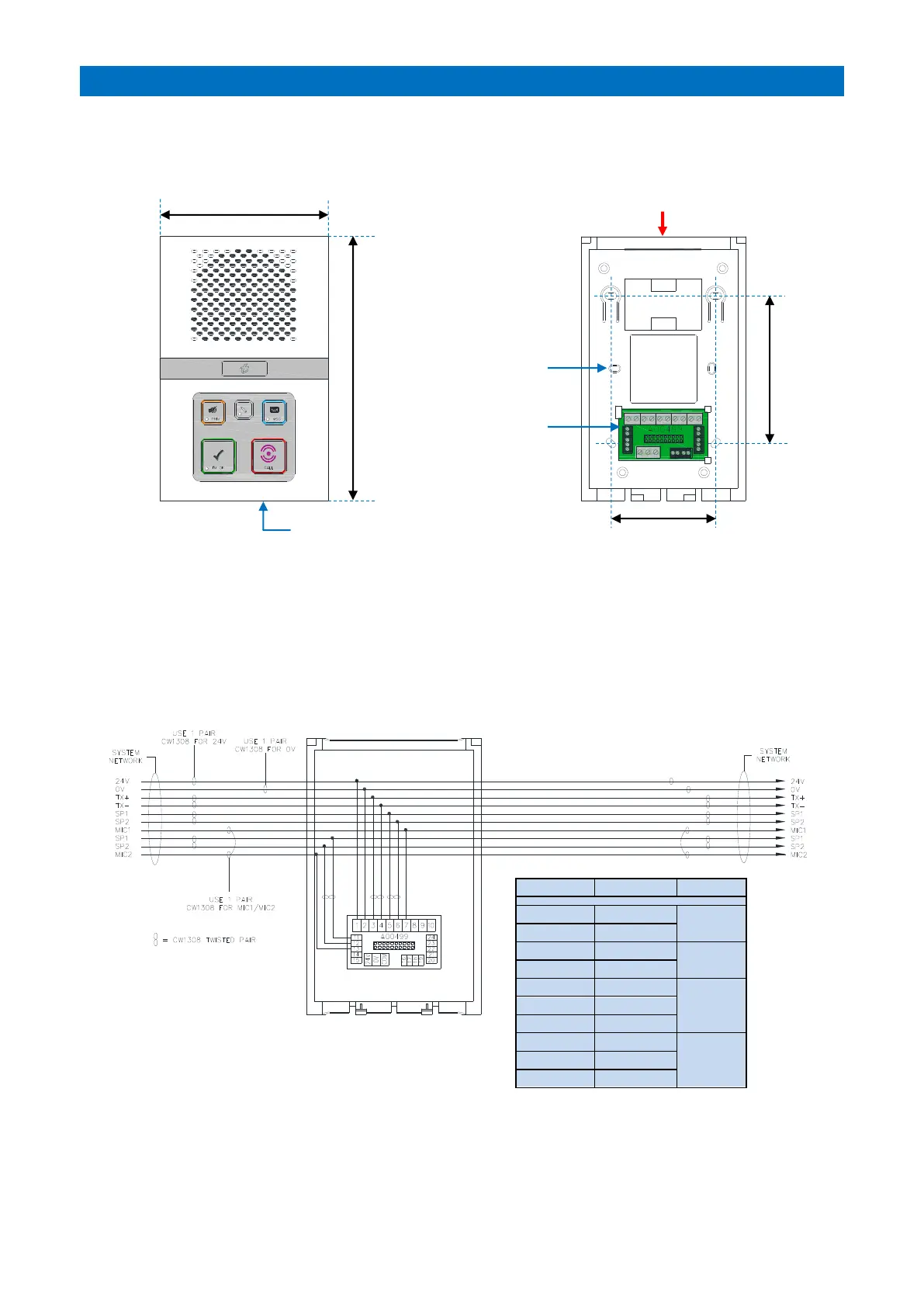
The intercom unit should be wall mounted in a central location within each dwelling. Screw fix the intercom rear
section securely to the wall using the 4 holes marked “A”. The 2 holes marked “B” can be used for an embedded box.
Ensure the case is not twisted as this may prevent the lid fitting or connectors aligning correctly.
The network cable should loop-in and out of each intercom via the cable entry channel on the top or the square hole
in the rear. Wherever possible avoid cable entry from below as this may interfere with the operation of the
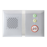
emergency pullcord, also keep the microphone hole on the lower front face free from obstruction. Cable clips are
provided in the rear to retain spare cores and prevent possible short circuits when the intercom front is fitted.
INTERCOM TERMINATION
The system network wiring is terminated on the interconnect board in the rear section of the intercom as shown
below;