INSTALLATION
Network Receivers should be sited in a dry secure area; they are NOT suitable for outdoor locations.
Network Receivers should be mounted so the antenna is vertical, as high as possible and free of immediate
obstruction from concrete, steel work or other electrical equipment.
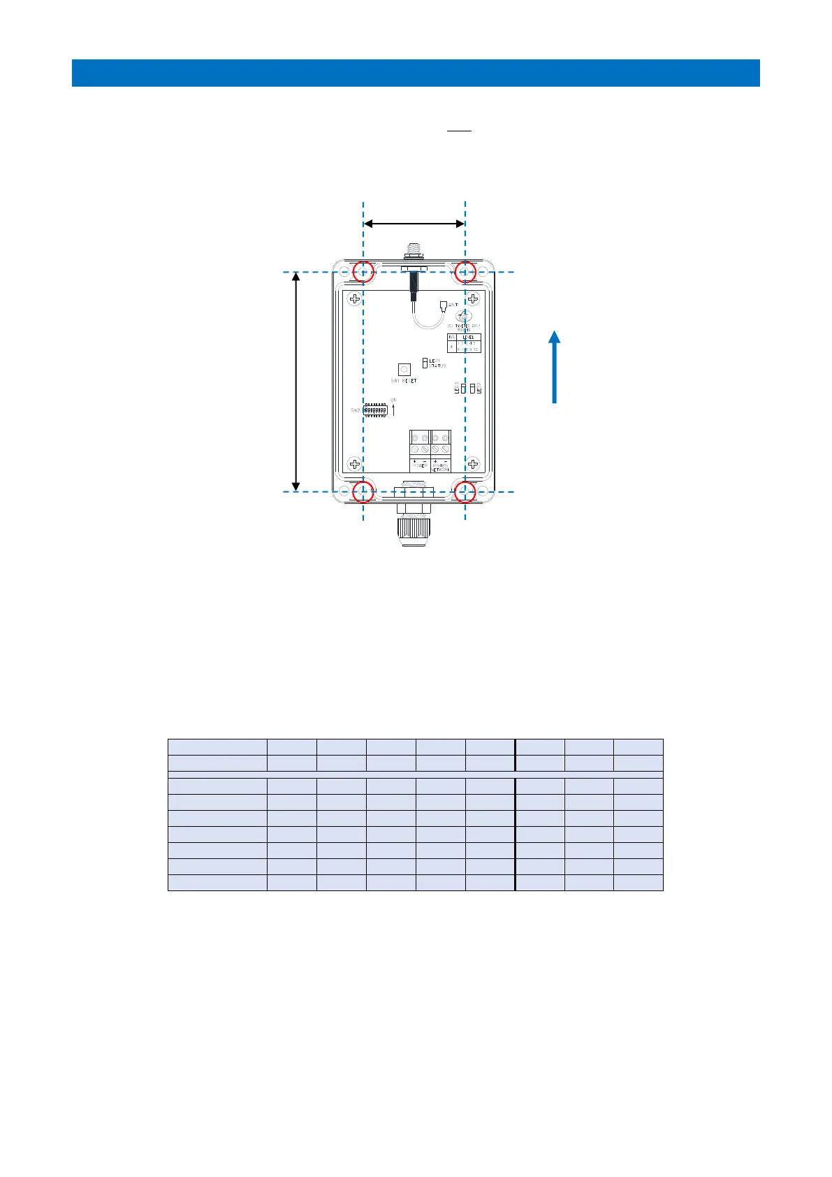
Fix the Network Receiver to the wall with 4 x Pozi screws through the 4 fixing holes “A” shown below.
TERMINATION
Cable entry should be through the cable gland on the lower face. Network Receivers require a 24V DC power supply
and RS485 data connection from the Advent XT2 system network using a 2 pair CW1308 cable. See Tynetec Drg No.
ZXT900 sheet 5 for wiring connections.
ID SETTING (SW2)
DIL switches 1 to 5 are used to set a unique Network Receiver ID.
ID’s are set in Binary, they must start at 0 and run sequentially to 31 max – do not duplicate ID’s.
DIL switches 6 & 7 are not used.
DIL switch 8 must be ON for XT2.
RESET BUTTON (SW1)
Always press the reset button after DIL switch settings have been changed.
LED’s
Status LED1 will flash green when a Telecare radio transmission received.
LED’s 2 & 3 indicate the NTR is connected to the RS485 Bus;
LED2 (yellow) should be permanently illuminated; LED3 (red) will flash when data is sent to the XT2.
PROGRAMMING
The total number of Network Receivers must be set programming - see the RS485 Network Setup section of the
Advent XT2 Programming Manual (Doc No. FM0815).