Doc No. FM0804 issue 4 Page 41
23. DOOR ENTRY PANEL INSTALLATION
TERMINATION
See Tynetec Drg. No. ZXT900 sheet 4 for detailed wiring connections.
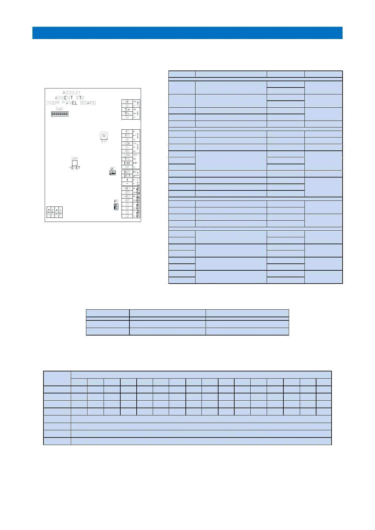
DOOR PANEL BOARD
RESET (SW1)
Press to restart panel and read DIL switch
settings.
DISPLAY CONTRAST (VR1)
Adjust for best display visibility.
LINK SETTINGS (LK1 & LK2)
LK1 selects a fail-secure or fail-safe lock type; a fail-secure lock requires power to unlock whereas a fail-safe lock
requires power to lock (fail open).
Fit for Fail-Secure Door Lock
Fit for Fail-Safe Door Lock
8 WAY DIL SWITCH SETTINGS (SW2)
DIL switches 1 to 4 are used to set a unique door panel ID (0 to 15). ID’s must start from ID “0” (all OFF) and run
sequentially. DIL switch 5 enables voice prompts, DIL switch 6 enables the relay output, 7&8 have no function.
OFF to disable voice messages, ON to enable voice messages
OFF to disable relay output, ON to enable relay output
PROGRAMMING
The number of door panels must be set in the RS485 Network Setup programming and the lock release time, ring
cycles, speech time, access codes, trade times and call transfer times must be set in Door Entry Setup programming.
See the Advent XT2 Programming Manual (Doc No. FM0815).
24V DC Supply for Door Panel
Common Trigger for IP1 & IP2
Clean contact relay output
which activates for the
duration of a door entry call
2 pair CW1308
to PTE & Door
Contact
External Lock input (N/O)
Common for T/G & EXLK inputs
1.0 mm pair
from Lock PSU
Warden Call Audio Channel 1
Warden Call Audio Channel 2
Door Entry Audio Channel 1
Door Entry Audio Channel 2